
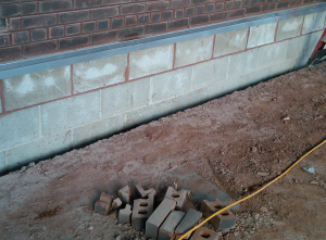
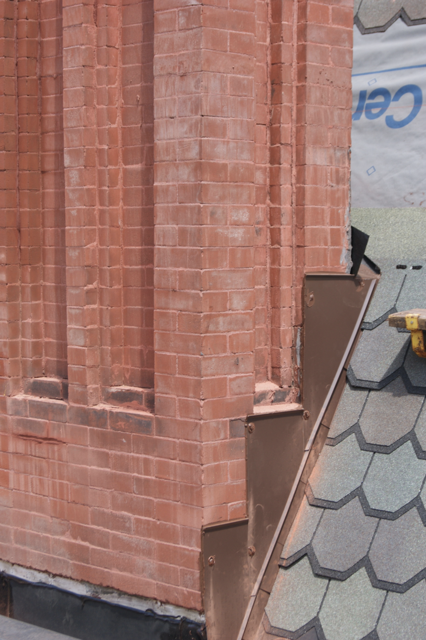
PHOTO 4: Instead of the construction in Photo 3, here, concrete masonry units were installed below the counterflashing receiver. If ever exposed, CMU will readily take on water. CMU walls also can excessively absorb adhesives and two applications are recommended.
This time, we’re dealing with a structurally sloped roof deck at 1/4 inch per foot toward centrally located roof drains. The roof width is 48 feet. Tapered insulation saddles between roof drains set 24 feet off the masonry wall. The roof is composed of cover board and bead-foam insulation. This is ASHRAE Climate Zone 5, which has an R-30 minimum.
- To meet code, thermal insulation totaling 5.2 is required. I suggest that this be in multiple layers, say 5 inches.
- With the drain being 24 feet from the wall, tapered insulation saddles will need to be 16 feet in width at 1/2-inch-per-foot slope (saddles need to slope twice the main slope to be effective). Thus, tapered at 1/2 inch per foot for 8 feet is 4 inches, plus the 1/2 inch starting thickness. Total thickness is 4 1/2 inches of ta- pered insulation at the ridge.
- Cover-board thickness is 1/2 inch.
- Bead-foam thickness is 3/16 inch for each layer. Let’s assume three layers, so about 5/8 inch.
» The roof deck will drop 6 inches from the roof edge to the low point.
» The height of the flat and tapered-insulation saddle at the wall is 10 5/8 inches; we’ll say 11 inches, which will be approximately level with the roof edge with its 5 inches of insulation.
The through-wall flashing should be at ±19 inches (11 inches of insulation plus 8 inches for roof base flashing) above the low point of the roof deck. The exact dimension needs to be worked out in the wall section.
As noted with the previous example, the location and height of the through-wall flashing should be placed on the building section and/or wall section because the mason, which will be on- site prior to the roofing contractor, will need to know this information.
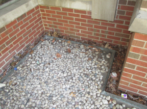
PHOTO 5: Twenty years ago, Hutch had to be creative when the through-wall flashing could not be raised and the roof surface rose above the wall flashing. In this photo, an interior gutter (with roof drains) was designed at the base of the wall below the through-wall flashing. It has performed well for decades.
With the required height for the through-wall flashing, based on the roof insulation, one can begin to detail the roof to masonry wall. For our discussion, we will assume the roofing is a single-ply membrane. The first challenge is to draft the condition correctly: roof deck location, support structure, angle at the wall, wall components, appropriate cavity spaces, wall insulation (should run down below the roof deck).
Thinking about how the wall and roof will be constructed, the sequencing is helpful. If you are not familiar with the construction of buildings, get yourself out in the field, watch and learn.
Following are key components of the detail to be shown:
Draft the detail at a minimum of 3 inches equal to 1 foot. Anything smaller will not allow for the appropriate level of detail to be shown.
- Through-wall flashing membrane is a soft, flexible material and prone to sagging if not supported at wall cavities. Thus, the wall cavity will need to be a bridge with the metal counterflashing material or closed with insulation.
- The counterflashing material should be compatible with the mortar and lime. Anodized aluminum and galvanized steel have the potential to corrode. Stainless steel and copper traditionally have been used.
- The metal gauge needs to be thick enough to offer strength and thin enough to allow for multiple bends.
- Show the counterflashing receiver set in continuous butyl sealant on the masonry.
- The through-wall flashing material, if not sheet metal, is recommended to be a self-adhering membrane.
- The through-wall flashing membrane should extend back to the masonry back up, be formed tight in the corner, extended up and over the CMU block above—typically 8 inches—and extended at least 3 inches back on the horizontal.
- Through-wall flashing laps: Experience shows us that laps can open, typically because they do not get primed and they are not mated tightly into corners. Thus, we require all laps be primed and a 6-inch cover strip of flashing material be applied, the edges of which are caulked.
- Premolded interior and exterior corners are recommended over field-fabricated because of the varying level of workmanship in the field.
- To weep the wall, I recommend cell vents instead of cotton ropes, which calcify over time. The cell vents should be shown atop the through- wall flashing, not atop a bed layer of mortar.
- If the mason contractor is on the ball and the roofing contractor willing, some membrane base flashings can be placed below the through-wall flashing and “hung” to be tied into the new roof system to eliminate the termination bar.
» In the sheet-metal and flashing section, specify the fabrication of the counterflashing receiver and provide it to the masonry contractor for installation.
» In the masonry section, specify that the mason is to install the counterflashing receiver provided by others.
Note that the mason is to provide needed dimensions, especially if the receiver is covering a cavity.
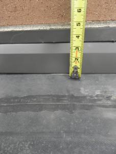
PHOTO 6: Four inches of additional insulation are going to be added to this existing roof, which Hutch designed 25 years ago. The new insulation will require raising the interface of roof base flashing and masonry through-wall systems.
» I suggest that not only should the specification call for priming of the substrate, but also that this be noted on the detail.

Be the first to comment on "The Integration of Roof and Brick Requires Concise Details"