
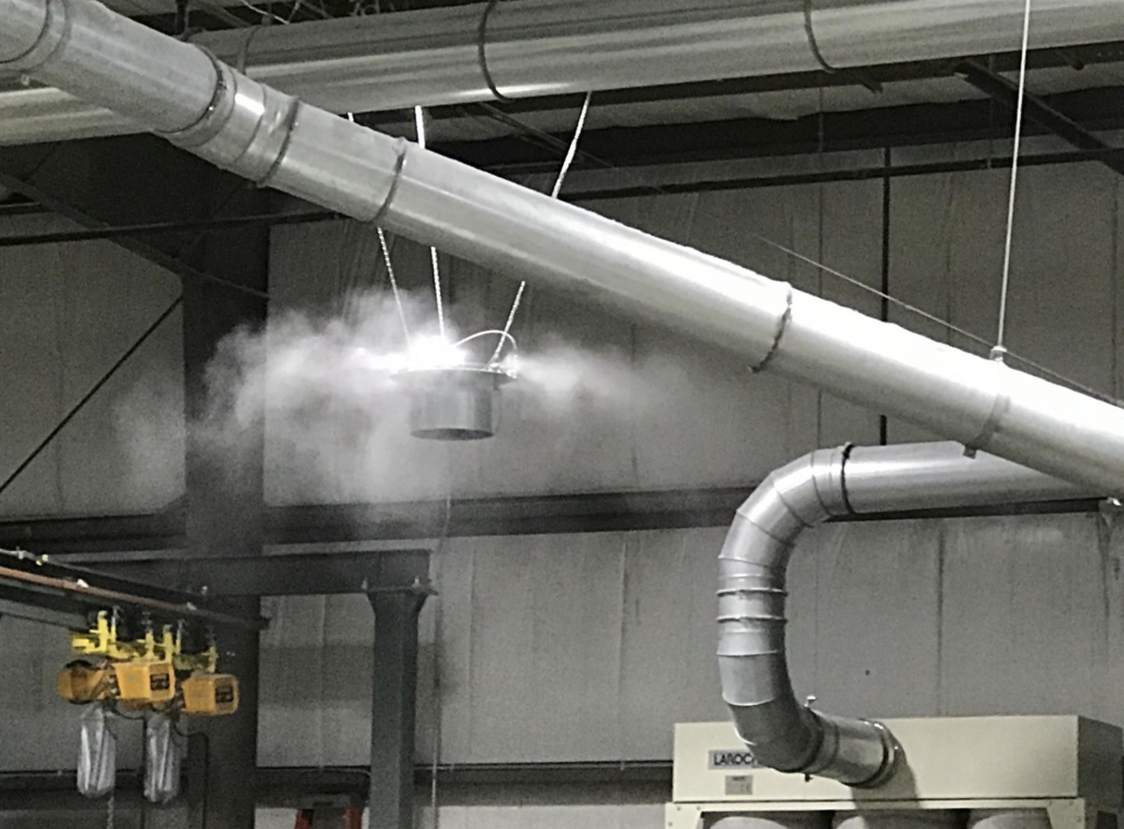
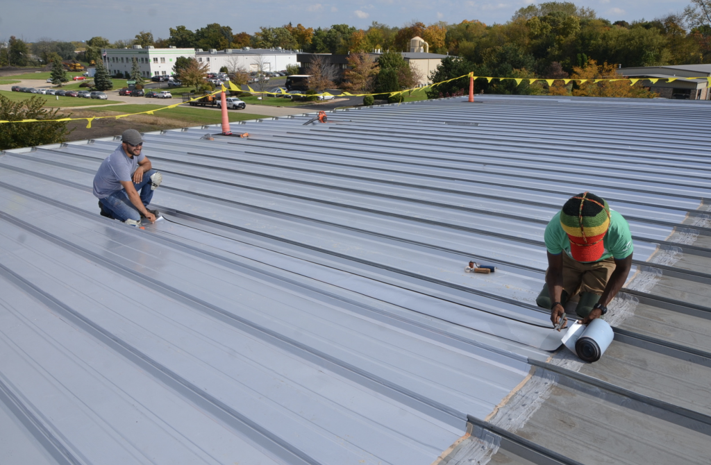
The client said, “The roof leaks in the dead of winter.” Interesting when the exterior ambient temperature is below zero. The client’s firm had purchased the metal building several years earlier and water had come in every winter. A key piece of evidence was that the original building was used for storage. The new entity purchased the building for manufacturing. Not just manufacturing, but manufacturing of medical-grade textiles that require the use of humidity to reduce static electricity. Not just humidity, but 90 percent relative humidity (RH), where visible water is sprayed into the air. (See Photo 1.) Interior temperatures routinely reached 90 degrees. Now, let’s see: 90 degrees with 90 percent RH inside, zero degrees outside, and 6 inches of vinyl face batt insulation compressed at the purlins with aged, open lap seams. Not good. The mission, if I chose to accept it, was to eliminate the leaking on a roof that was watertight.
Proposed Solutions
During my first meeting with the client, I was provided with proposals from roofing contractors and, sad to say, several roof consultants. Proposed solutions ranged from coating the metal, to flute filler and cover board with a mechanically attached thermoplastic membrane, to flute filler, 2 inches of insulation and adhered thermoplastic. None of the proposals identified the interior’s relative humidity and heat as a concern, and thus these issues were not addressed. So, a good part of the morning was spent educating the client as to why none of the proposed solutions would work. Imagine spending big bucks on a roof solution that would have only exacerbated that situation.
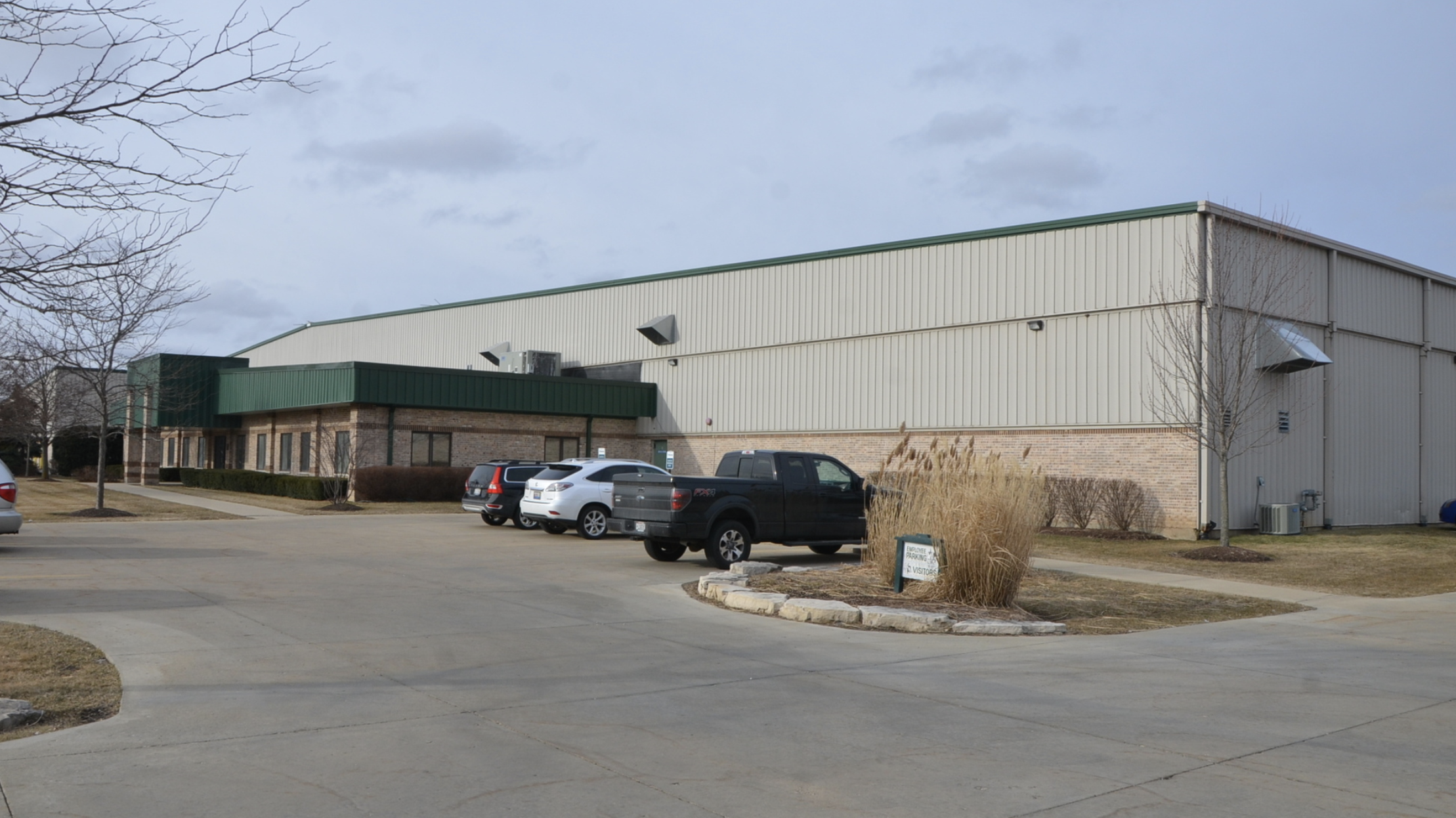
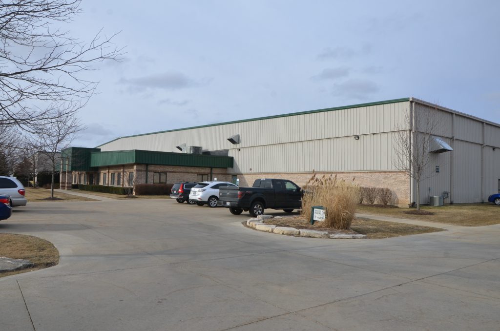
The existing building was a metal building by Kirby (similar to a Butler Building if that helps). The roof was a trapezoidal seam metal roof panel 24 inches wide on a low slope to an offset ridge. The panel runs from ridge to eave were 200 feet to the north and 100 feet to the south. The roof drained to a gutter on the north and lower metal roof on the south. The east and west roof edges were standard metal building rake metal. The walls were vertical metal siding with exposed screws. The roof and metal wall panels were set over vinyl faced insulation draped over purlins. While there was exhausting of the interior air — typically used in the summer — and some provisions for adding exterior air in the winter and summer, there was no overall mechanical control of the interior.
The Key Issue
While a freezer building has extreme energy low trying with every ounce of its being to pull hot humid air in, this structure has extreme energy high trying to “get out.” The warm, humid air is seeking every crack, split in the insulation facer, and open lap seam to move toward equalization. This warm, humid air was making its way to the underside of the metal roof panels, condensing, and running down the underside of the panel until it dropped off.
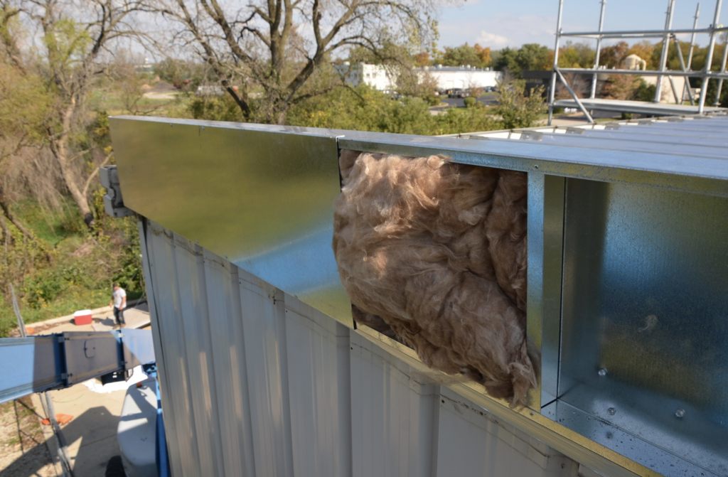
After time, the accumulation of the water in the batt insulation created a large belly until the adjacent lap seam broke and large amounts of water came cascading down. Soiled product had to be discarded. With rolls 5 feet wide and a 6 feet diameter, the losses could be substantial. Water on the floor was also a safety issue. Additionally, when this damage occurred the insulation layer now had an opening which sucked in even more interior air; the condensation increased and water dripping to the floor was an even bigger problem. This was occurring in numerous conditions, with the greatest accumulation of water in the insulation near the ridge. (See Photo 2.)
Determining the Solution
Prior to delving into a potential solution, a parti, or overall concept of architectural design, had to be developed. In this case I decided that the metal roof would become the vapor retarder for the new roof. Simple enough. If the metal roof is to become the new vapor retarder, the key was to keep it warm enough so that even if it came in contact with the interior air, it would not result in condensation. We did this by determining the dew point for several insulation scenarios and found that with the batt insulation still in place and 90 percent RH with a temperature of 90 degrees inside, with an exterior design temperature of minus 10 degrees, 6 inches of insulation above the 2.5-inch flute filler was required.
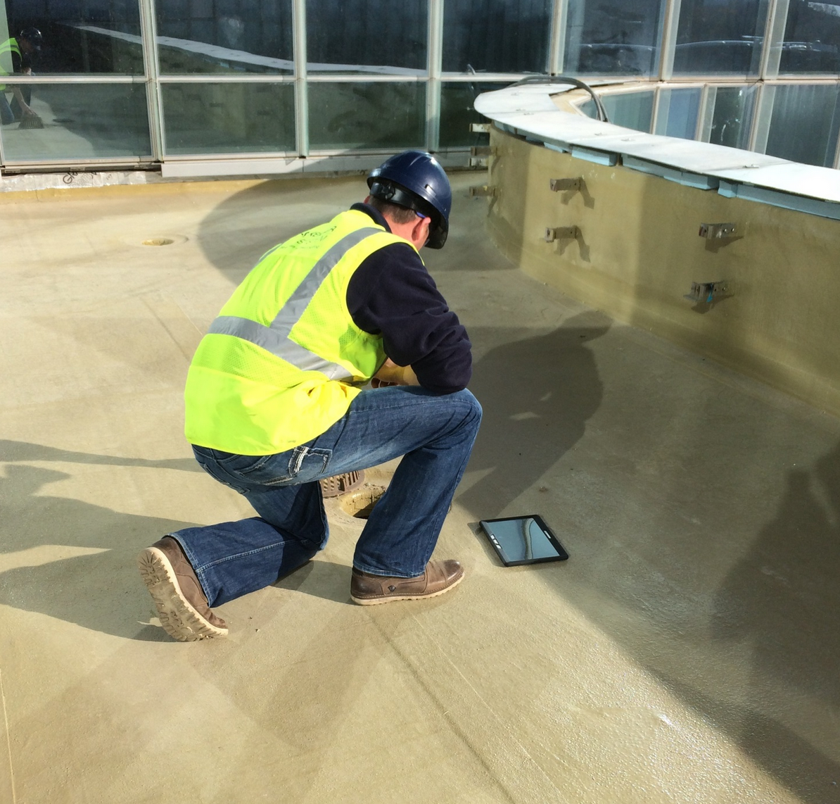
All roof system designs need to be thought of holistically, as the success depends on the sum of all the components working together. So, let’s start with the roof panel and structural system. Designers of metal buildings are notorious for minimizing each and every structural member to lower costs. A structural check found that the existing structure was able to handle the weight of a new roof system. Prior to proceeding, a mechanical fastener pull-out test was performed by Pro-Fastening Systems of Buffalo Grove, Illinois, an Olympic Distributor (need a special or standard anchor, these guys have it). The tests showed that the 22-gauge metal panel was able to engage the buttress thread screw.
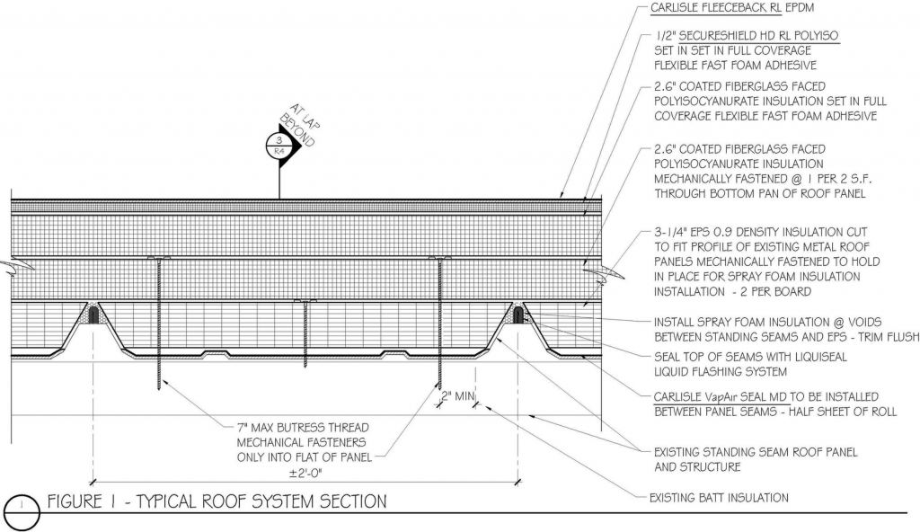
To be effective, a vapor retarder needs to be airtight — or for you purists, have extremely low or no permeability at all — and this metal roof had to function as a vapor retarder. The steel roof panel itself is impermeable, but the seams, though mechanically locked, have the potential under interior pressure to allow air to pass through. The seams had to be sealed. The mechanical fasteners penetrating the metal roof panel needed to be sealed as well. The roof transitions at the vertical rake walls, gutter and low roof also needed to be sealed. After looking at the standing seams, it was decided that they could not be assumed to be airtight, so we selected to seal them with a liquid flashing. As the mechanical fasteners would penetrate the panel, a bituminous self-adhering and hopefully self-sealing vapor retarder was placed on the panel. (See Figure 1 and Photo 3.) Transverse laps, removing the ridge cap and infilling the opening were all addressed. The rakes presented unique challenges which took some good thinking on how to seal. Ultimately, it was decided that a combination of removing the rake metal and installing a prefabricated roof curb and membrane vapor retarder would do the trick. (See Figure 2.)

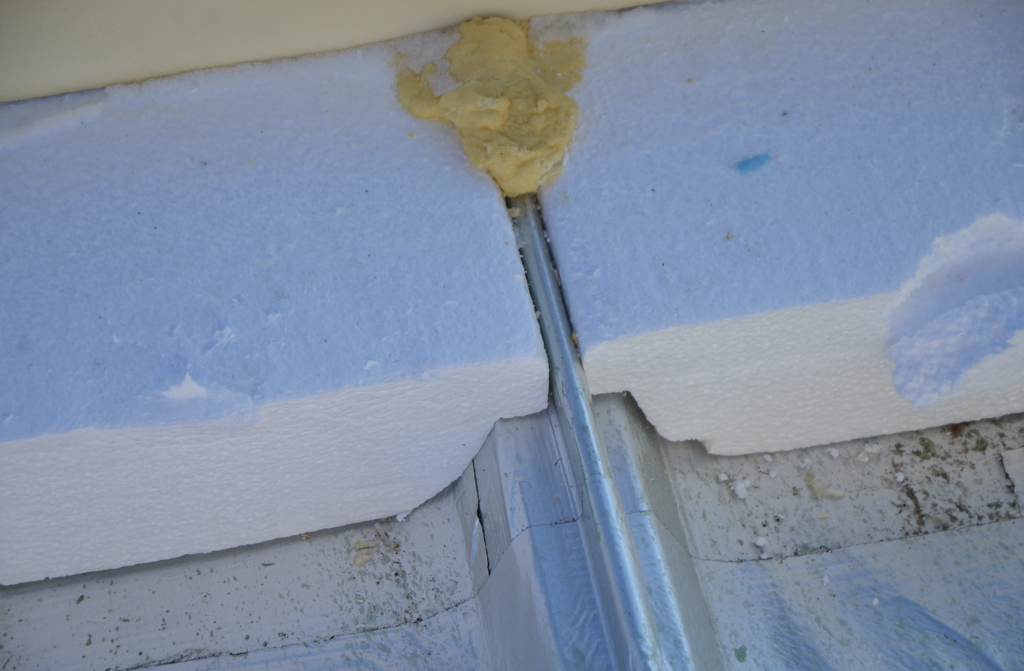
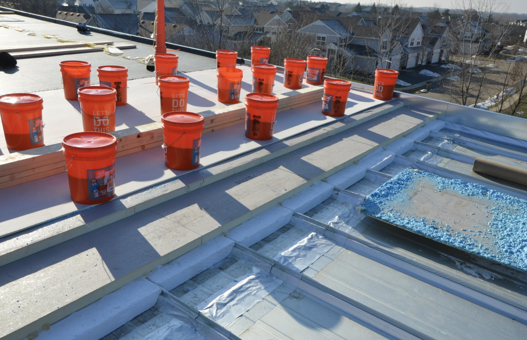
My initial thought was to begin the thermal layer with a layer of expanded polystyrene (EPS) on the deck designed to fit the trapezoidal seam profile. This left a void at the seams, so the void between the seam and EPS was sealed with spray foam insulation. (See Photo 4.) The insulation was then mechanically fastened. The thickness of the EPS was 3/8 of an inch greater in height than the standing seam to compensate for varying seam heights. Over the EPS, one layer of 2.6-inch fiberglass-coated faced, 25 psi polyisocyanurate insulation was designed to be mechanically fastened to the roof panel. The top layer of insulation was a 2.6-inch fiberglass-coated faced, 25 psi polyisocyanurate insulation, which was designed to be set in full spatter cover flexible polyurethane foam adhesive. A cover board with the receiver facer to which the membrane would be attached was designed to be set in a full coverage of splatter applied polyurethane insulation. (See Photo 5.)
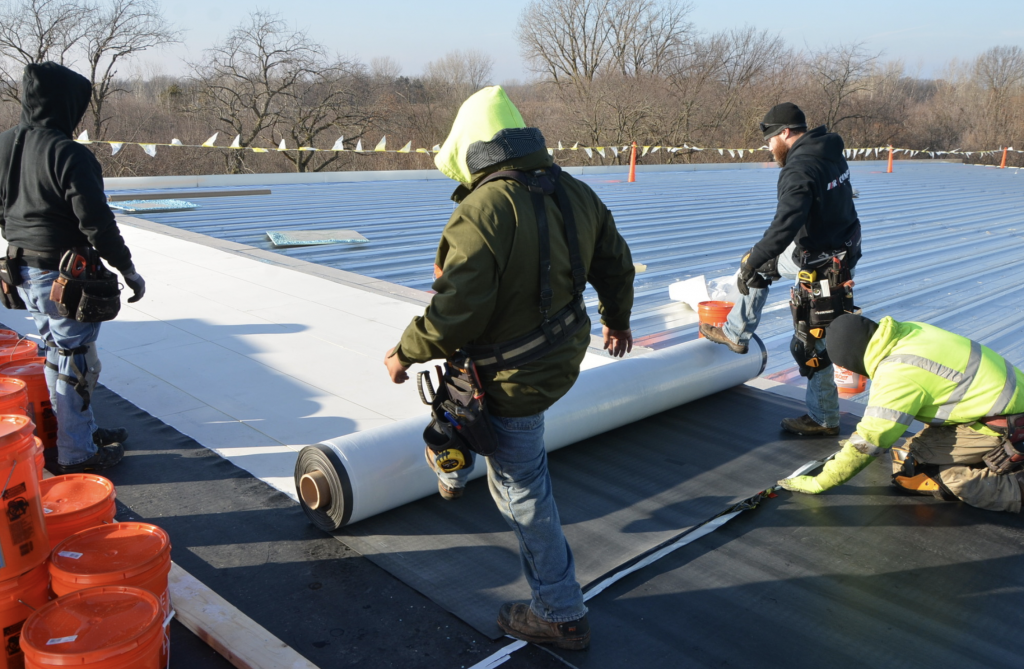
As the installation was to take place in late fall and during the winter, adhesive use was determined to be challenging if not impossible, so the roof cover selected was a 90-mil Carlisle FleeceBACK black EPDM. The fleece on the membrane would engage with a unique hook and loop facer and reduced by 95 percent the amount of adhesive required. (See Photo 6.) Six-inch seam taped end lap seams with self-adhering cover strips were designed, while the butt seams were also double sealed with 6-inch and 12-inch cover strips.
The rake edge was designed to be sealed at the top of the metal panels and raised with an insulated metal curb. (See Photos 7 and 8.) The wall panels’ reverse batten seams and bowed inward panel were designed to be sealed with a foam closure set in sealant. The architectural sheet metal on the rakes was a four-piece system of fascia and coping. The roof edge gutter was enlarged and reinforced to hold up to solid ice.
Construction
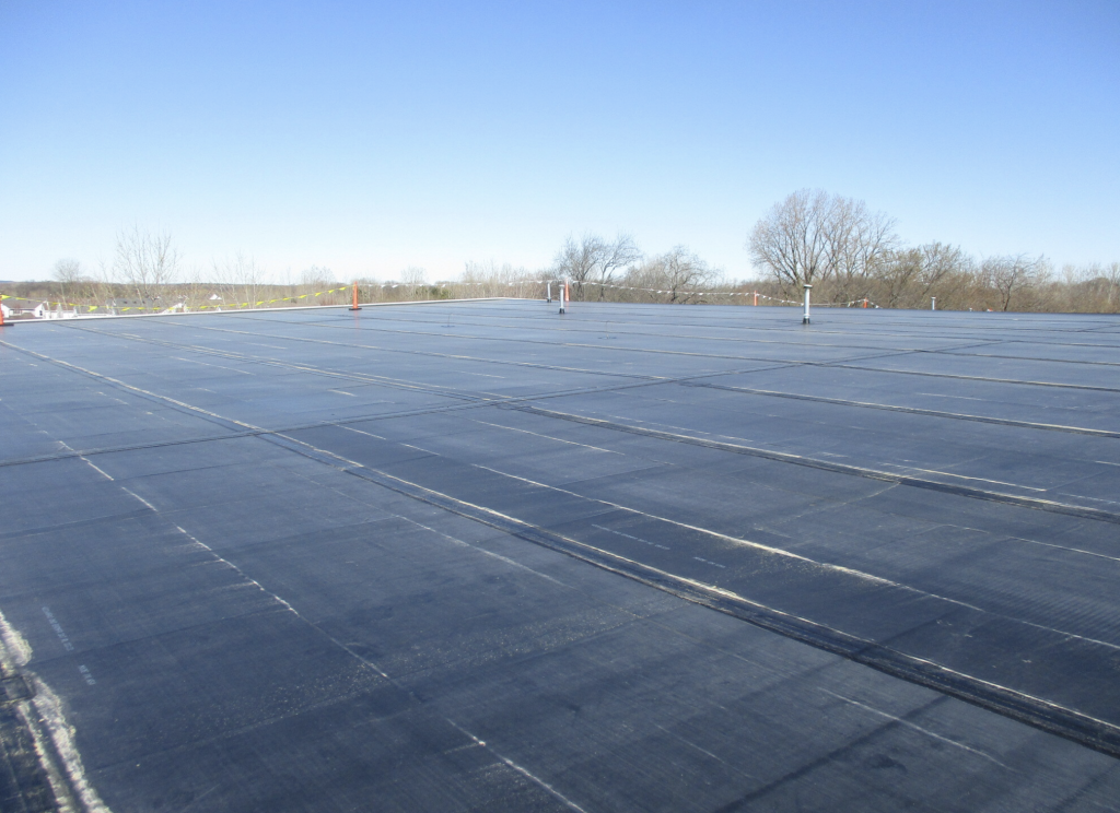
The project was bid out and AR Commercial of Aurora, Illinois, was selected. Work on the project began in October 2018 and was completed in April 2019. (See Photo 9.) Like any project, various miscellaneous items not anticipated arose, such as extreme cold early in the fall that precipitated the decision to mechanically attach the insulation in lieu of cold adhesive application. I also forgot about the residual water in the existing batt insulation. While we designed for 90 percent RH and temperatures of 90 degrees, we didn’t anticipate the 100 percent RH condition where the soaked batt insulation was located, which resulted in condensation occurring during the deep freeze. You’re never too old to learn something new. The batts were cut open, dried and all is good.
Sometimes you need a good roof over your head to keep you dry, even when it doesn’t rain.

About the author: Thomas W. Hutchinson, AIA, CSI, Fellow-IIBEC, RRC, is a principal of Hutchinson Design Group Ltd. in Barrington, Illinois. For more information, visit www.hutchinsondesigngroup.com.


Be the first to comment on "Case Study Reveals Key Lessons in Roof Design"