
How do I start an article on a topic that is so problematic, yet it’s not being addressed by designers, roof system manufacturers, FM, SPRI, NRCA or any other quality assurance standard? Like many transitions in the building industry, the use of metal studs in exterior wall construction and roofing in new construction developed out of the twin concerns of value engineering and cost reduction. It has crept silently forward without any real consideration of the possible effects this less robust construction method would have on roof system performance.
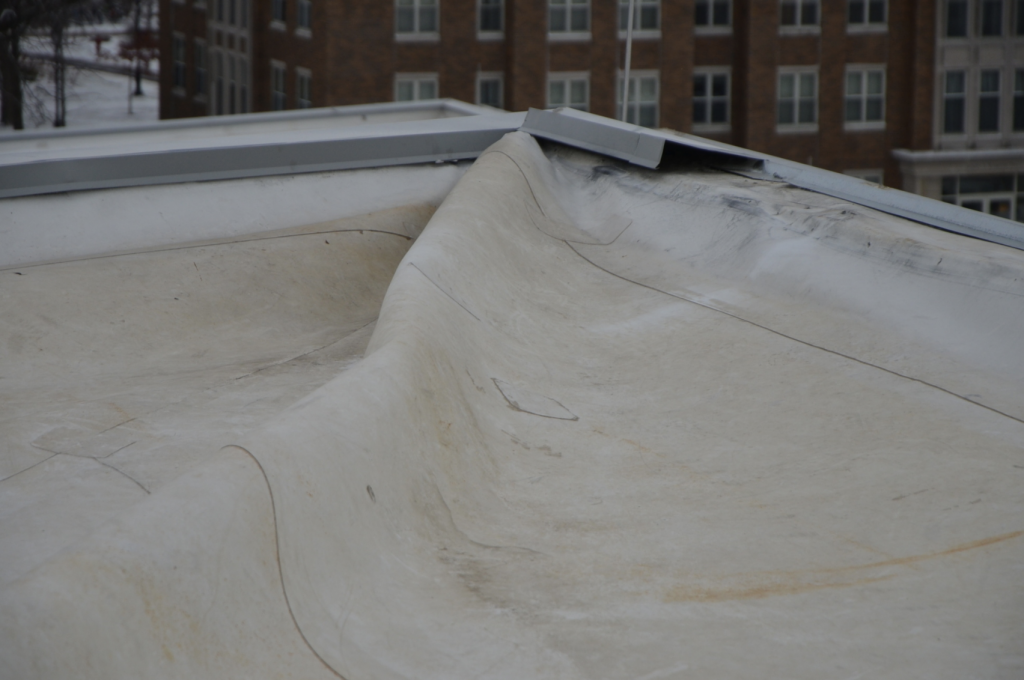
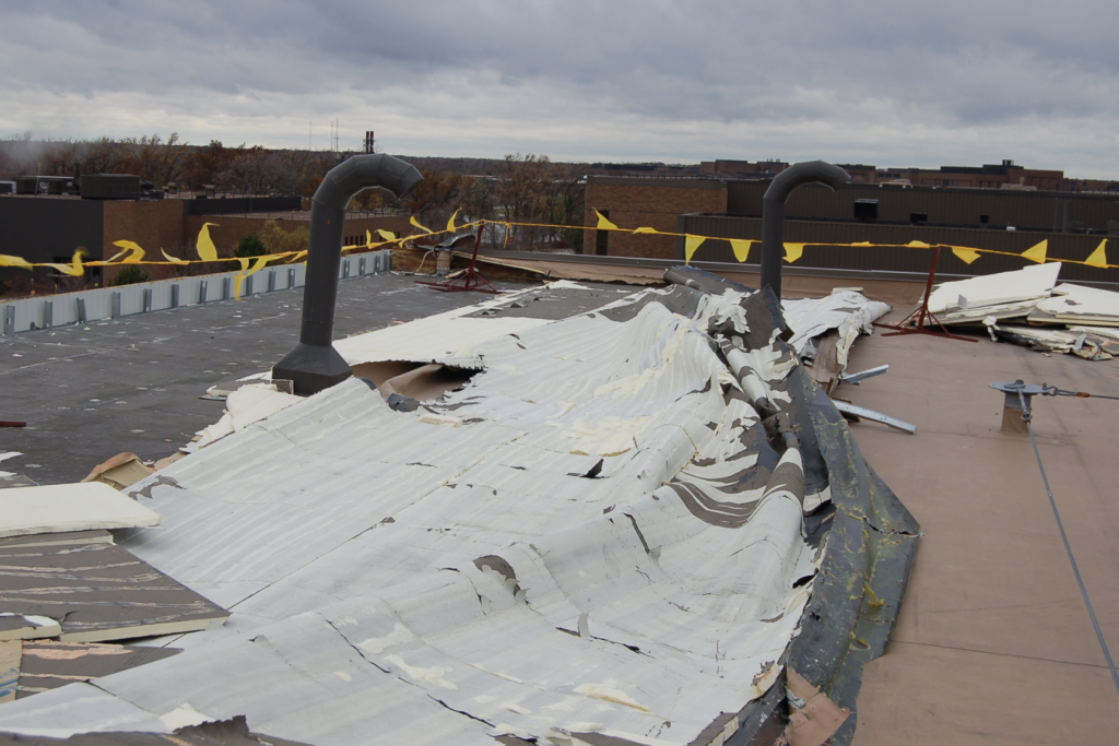
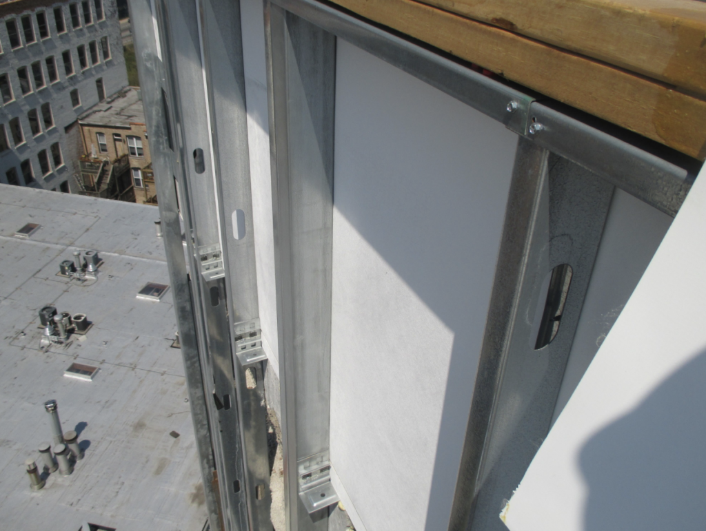
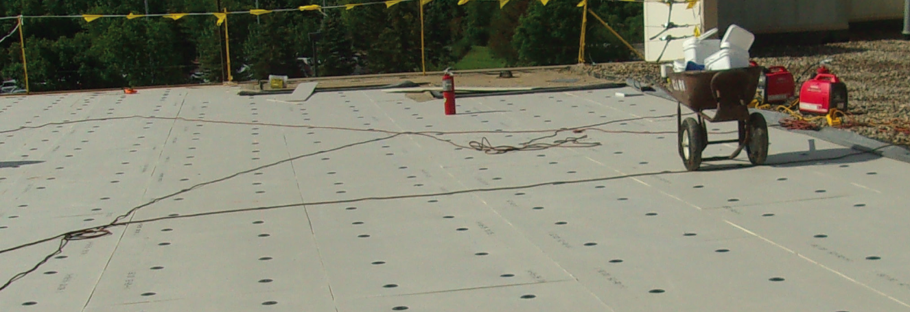
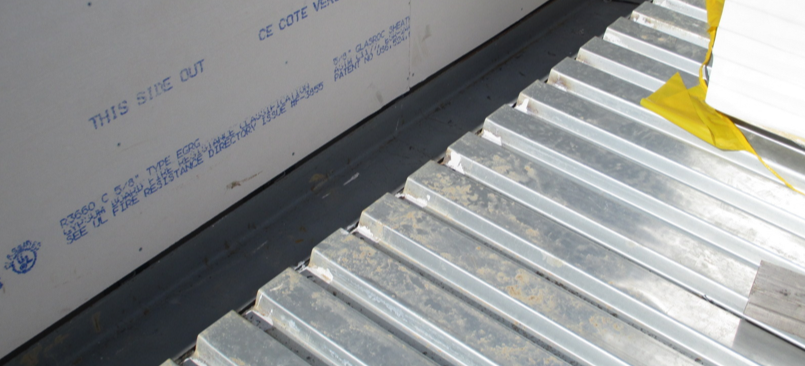
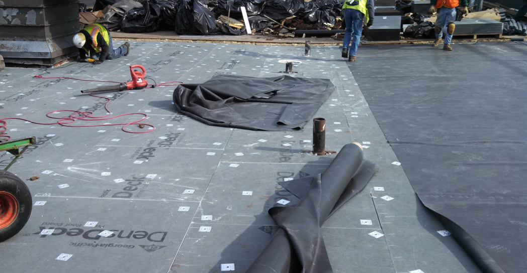
You would think that someone along the line would say, “Hmm, I wonder how strong, effective or appropriate a screw fastener through a modified gypsum board sheathing would be?” Let me answer that question: Worthless. (See Photos 1-3.)
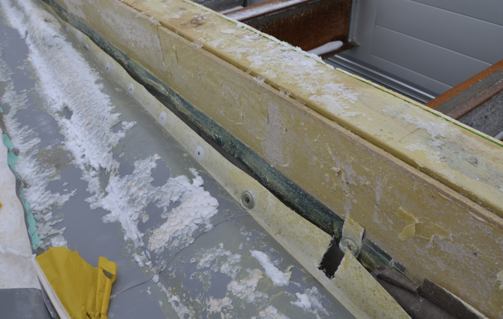
There are many issues with metal stud wall construction as it relates to roofing: air drive, moisture, interior pressures, and membrane adhesion to substrate, just to name a few. This article will address only one concern: The base anchor attachment horizontally into steel stud walls, most often clad with a modified gypsum substrate board. (See Photo 4.)
Why Is This a Concern?
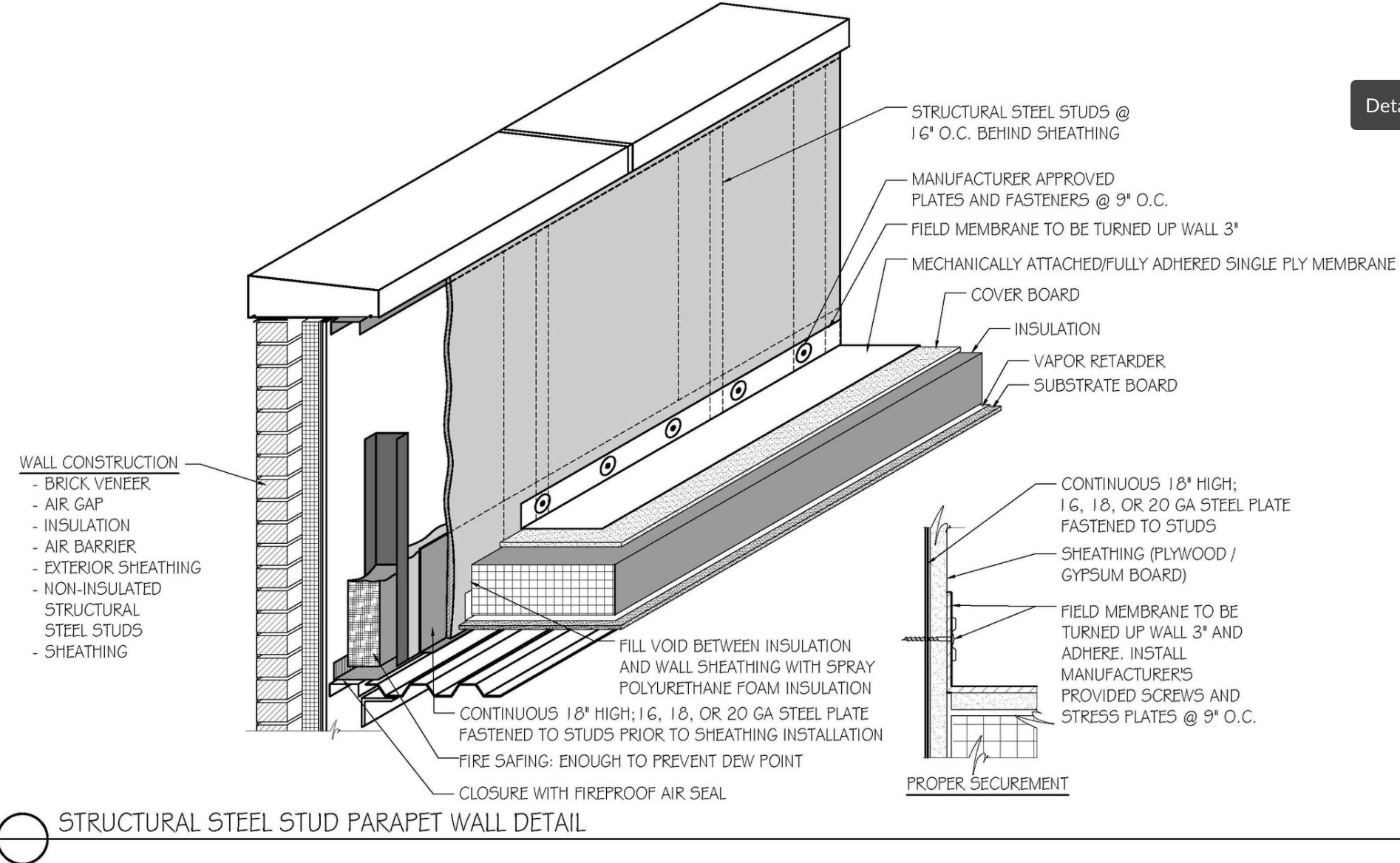
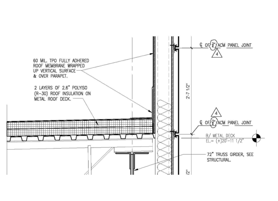
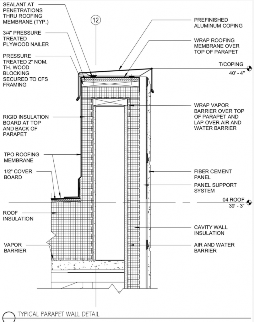
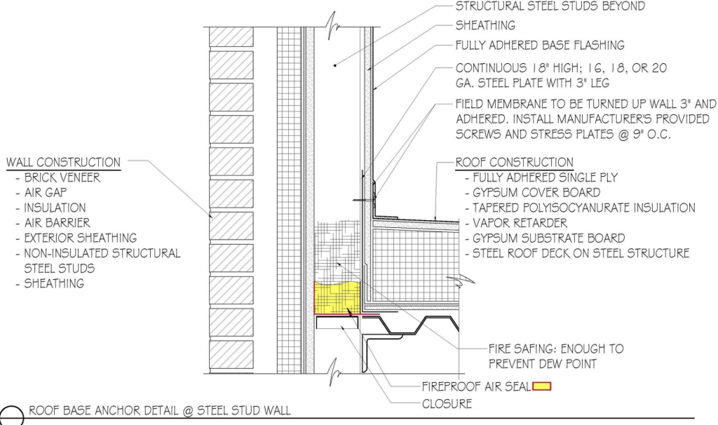
Problems often begin in the design phase when the condition is not detailed appropriately. (See Figures 1 and 2.) The architect/engineer/ designer shows some lines and figures that the roofing contractor or manufacturer will make it work — and specifies a 20-year warranty. The designer’s first mistake is to think that contractors and manufacturers design. They do not.If I were a betting man, I would guess that 99 percent of the specified wall substrate for roof-side metal stud walls is a product that is unacceptable for roofing base flashing application. You’re smiling now, aren’t you? Been there, huh? Designers often have little knowledge as to how a roof system, or even a roof membrane, is installed, and thus don’t even realize the errors of their ways. If they did, they might realize that at the very least a base anchor attachment is at 12 inches on center, and at some time a screw is going to have to go horizontally into the inappropriate sheathing substrate. Concept 1: Architects design. I know this is scary.
Architects and designers who do not prepare project-specific details seem to love manufacturers’ standard details, which are provided as a baseline for developing appropriate project-specific details. They are not an end all, and thinking they are is a huge mistake. Another common mistake is not realizing that manufacturers do not have a standard detail for base anchor attachment into metal stud walls. This is probably because they never imagined that anyone would really try to anchor into such a poor substrate. Concept 2: Manufacturers produce products that can be assembled in a roof system; they do not design.
Oh, but the contractor will make it work. Yeah, right. Concept 3: Contractors install materials provided by the manufacturer, as specified by the designer; they do not design. Are you starting to see a trend here?
You can now see the conundrum of the blind leading the blind.
So, to be clear:
- Architects: Design
- Manufacturers: Produce products
- Contractors: Install materials
To say it a bit clearer:
- Architects: Design
- Manufacturers: Do Not Design
- Contractors: Do Not Design
Read it again and see where the responsibility lies. Of course, the manufacturer needs to produce quality materials, which sometimes does not occur, and contractors need to install the materials correctly, which sometimes does not occur.
Pull-Out Strength
So that we can get this detail correct, let’s look at pull-out strengths of various materials. But let’s start with trying to determine what pull-out resistance is required. For our example, let’s use 60-mil TPO, a common roofing membrane on new construction projects.
Manufacturers report on their data sheets for 60-mil TPO tear strength of around 130 pounds of force (lbf). The test for this isn’t pulling the membrane out from base anchors, but it’s a good start for our discussion. I suspect that if base anchors are attached at 9 inches or 12 inches on center that the series of fasteners will elevate this value.
Given that we know that the tear resistance of TPO with a series of fasteners is greater than the ASTM D751 Tearing Strength test, I will suggest that we need a substrate with a pull resistance greater than 260 lbf, or twice the tear strength value. After that the membrane will tear itself out from around the fastener plate.
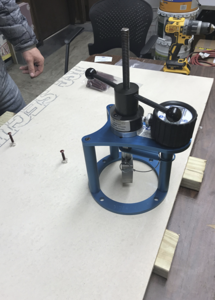
To determine the pull-out resistance of various sheathing materials, I had the pull-out resistance of a base anchor screw tested on several materials by Pro-Fastening Systems, a specialty distributor focusing on commercial roofing in the Midwest that provides certified pull-out testing. Three pull-out tests were performed on each material. (See Photo 5.) The mean resistance values are as follows:
1/2” plywood: 422 pounds
5/8” plywood: 402 pounds
1/2” glass-faced gypsum: 13.3 pounds
1/2” integral fiber reinforced gypsum: 110 pounds
22-gauge steel deck: 646 pounds
22-gauge acoustical steel deck: 675 pounds
18-gauge steel stud: 1,086 pounds
26-gauge metal stud: 646 pounds
16-gauge steel plate: 1,256 pounds
18-gauge steel plate: 978 pounds
20-gauge steel plate:724 pounds
22-gauge steel plate:625 pounds
So as a starter we eliminate all the typical gypsum-based sheathing materials from being used at the base of the roof. I’m not keen on plywood either, as over time, as the plywood dries, the pull-out strength lessens. Additionally, gluing to wet plywood never works well.
Designing the Base Anchor on Metal Stud Walls
The concept is simple — provide a substrate with a pull-out resistance greater than the tear strength of the roofing membrane attached in series. So, let’s pretend you’re drafting. Come on now, get your paper out, a number 2H pencil, a parallel rule and triangle to get the feel of the detail — no CAD for you today. For our example, assume you’re in the Chicago area, minimum R-value of 30, tapered insulation and 24 feet from the drain to the wall.
First, draft and show the roof deck and your wall, roof edge and studs. Now you’re ready to start your detail. First go to your roof plan, where you have shown all the tapered insulation, and calculate what the thickness will be at your studs. Remember, code requires thickness within 4 feet of the drain. For our detail, you’re near Chicago and thus the height of a tapered insulation layout might be as follows. For the R-30 at the roof drain with a substrate board, insulation and cover board, let say for simplicity it’s 6.5 inches (1/2-inch cover board + 5.4 inches of code-required insulation + 1/2-inch cover board). Now you need to calculate the tapered insulation. For our example, the distance from drain to wall is exactly 24 feet. With a taper of 1/4-inch per foot tapered that is 6.5 inches (1/4 inch x 24 feet = 6 inches, plus the 1/2-inch starting thickness of the tapered). If you plan to use foam adhesive, add 3/8 inch per layer of foam, and be sure you understand all the layers in a tapered system. So, at the wall, the insulation will be approximately 13 inches. With the screw and plate anchor say, 2 inches above the insulation surface, we have a height of 15 inches. So, let’s say we need a substrate capable of pull-outs at least 18 inches in height from the roof deck.
Now, I know you are thinking, “OMG, 18 inches — I can cut in a little 6-inch strip at the top of the insulation.” Don’t do it. The strip will not have any continuity or strength and will often buckle under load. Additionally, this continuous substrate piece needs to be placed on the stud.
Back to your drafting board. Draw in against your stud a continuous 16-, 18- or 20-gauge galvanized steel plate. Depending if the membrane is to be taken up and over the stud wall or terminated some distance above the roofing, the rest of the wall can be clad in less robust materials. Pick any substrate that is roofing membrane compatible and place it over the continuous steel plate and studs above. Tell the contractor how often you want the substrate anchored.

Draw in your substrate board, vapor retarder, insulation (and don’t forget to show and call out the spray foam seal between the insulation and wall, as there is often a void). Bring your membrane to the wall, turn it up 3 inches fully adhered to the substrate and show a plate and screw. Call this plate and screw out and note the spacing on the drawing; I’ve never seen a spec up on the roof. The base flashing can now be delineated coming down over the anchors and out onto the flat. Depending on the material, show a weld or seam tape. Now compare your detail to Figures 3 and 4. Who has properly designed the condition?
Remember
There are many issues and concerns with steel stud walls and roofing. This issue with substrate cladding in regard to the interface with the roofing system is only one that I see again and again on projects that have wind damage issues. By carefully designing the roof termination conditions, taking into account all the possible impacts and then detailing the conditions properly, your standard of care can be met and the owner well served.
About the author: Thomas W. Hutchinson, AIA, FRCI, RRC, CSI, RRP, is a principal of Hutchinson Design Group Ltd. in Barrington, Illinois. For more information, visit www.hutchinsondesigngroup.com.

an excellent article by Mr. Hutchinson as usual. Thanks for elevating our industry!