
If I were the Roofing God for a day, what would I change? Oh, where do I start? First of all, there would be none of this “you should,” “can,” “may” or “it is recommended” nomenclature. I would have commands: Thou shall do the following.
Freezer Buildings and Block Ice Insulation
I have never opened up a roof over a freezer building that wasn’t solid ice between the insulation joints. How does this travesty occur? Ignorance? In part. Naiveté? Yes. Who is guilty? Whoever is the roof system designer. Most designers should know that there is an enormous moisture drive from the exterior to the interior. This drive is not a passive movement, but a huge, sucking pressure. It’s like there is a shop vac in the interior trying to pull in outside air. But designers fail to realize that the first sources of interior moisture intrusion into the roof system are moisture migrating out from exposed soil until the concrete slab is poured; moisture coming from the interior concrete floor slab; and latent air moisture (relative humidity) in the interior air before the freezer is operational.
We in the roofing industry are very good at keeping water out of the building. It’s the influx of air that is destroying these roofs shortly after bringing the freezer online. So how is the air getting in? Oh, let me count the ways: (1) though the unsealed membrane at the roof edge; (2) past beveled precast concrete joints at the roof edge; (3) below perimeter wood blocking at the roof edge; and (4) up through metal wall panel joints.
Stopping air transport to the interior is key. Most designers believe that the roof membrane performs as the air/vapor barrier. In the field of the roof, perhaps, but their lack of knowledge about roof material characteristics and proper installation methods often leads designers astray. The perimeter becomes the weak link.
Let’s look at some common design mistakes:
1. In recent years, designers have revised roof membrane selection to reflective roof membranes, in part to garner a LEED point. The trouble is that these membranes are substantially ridged/stiff and can be difficult to turn over the roof edge, adhere and seal, so they are often barely turned over the edge and nailed off. The lack of a positive seal (that would be achieved by adhering the membrane to the perimeter wood blocking and wall) allows air to move up below the membrane.
2. When precast concrete panels are used at the walls, the joints are often beveled. What happens at the roof edge? The bevel extends right up to the perimeter wood of the coping that is straight and parallel to the outside wall face. The bevel becomes a gutter to channel wind up the wall to the underside of the gutter, gravel stop or coping. In a situation like the one outlined in No. 1 above, the wind can move in below the roof system.
3. When perimeter wood blocking is placed in a horizontal position at the roof edge, the underside of the wood blocking needs to be sealed. A non-curing, gun-grade butyl, applied in several rows, works well, such that when the blocking is secured to the wall, the underside of the blocking is sealed. Be aware of uneven substrates that will require additional sealant.
4. Metal wall panel joints are another potential problem spot. Ask a metal wall panel installer why they are only sealing one of the two exterior male–female joints and you are likely to hear, “because the exterior joint completes the vapor retarder” (which is on the exterior of the building when perfect). Technically they are correct. However, getting a perfect sealant joint to create a complete vapor retarder is not so easy. Think of how sealant is applied. The installer squeezes the caulk gun handle and the sealant oozes out in a thick bead, which can vary in thickness as the gun is drawn along. As the trigger is squeezed and the gun moves, the sealant bead decreases in diameter, and then the gun handle is squeezed again and a thick bead oozes out, and so on. At the end of the sealant application, the thinned-out bead is often not sufficient to properly seal the panels where they are engaged. Condensing water weeps out of the joints in the interior in cold storage areas and results in interior ice on freezer buildings. The sealant, whether factory applied or field applied, is not located at the exterior plane of the panel, but recessed in the outer tongue and groove joint, leaving the potential (almost a guarantee) that there will be a vertical “chimney” of about 1/16 of an inch that can channel air up under the membrane turned over the wall panel.
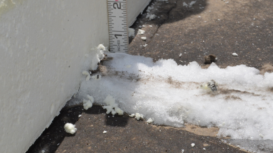
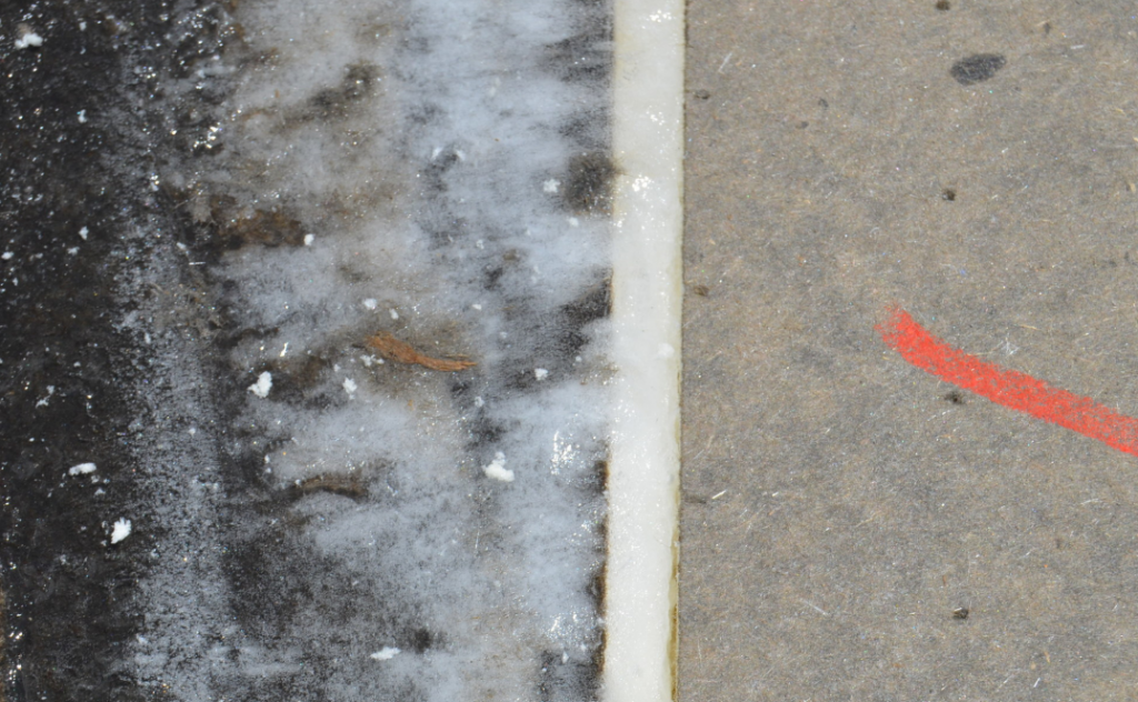
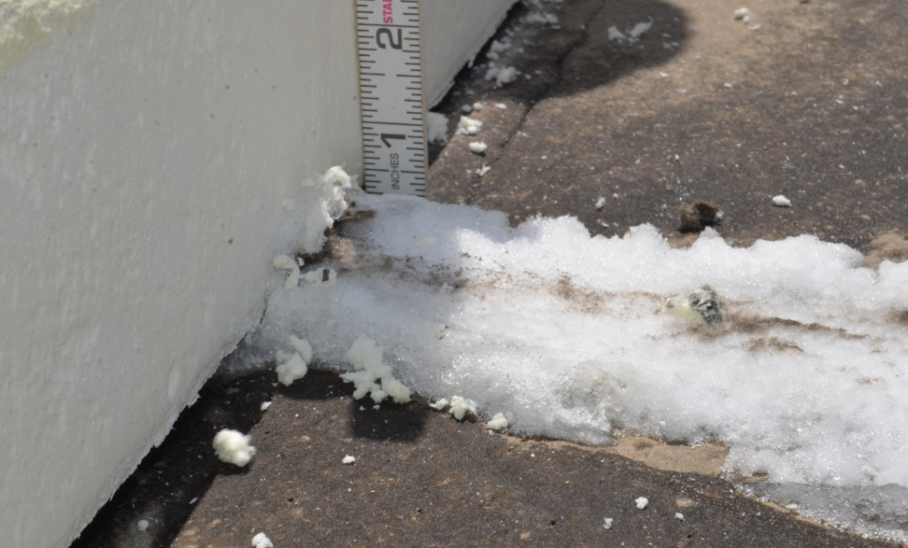
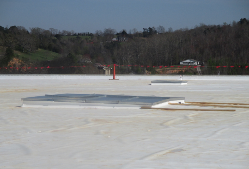
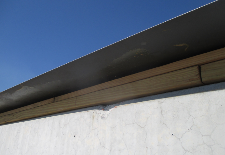
A quality vapor retarder (those of you thinking polyethylene, think again) placed on the roof deck will protect the thermal layers from vapor intrusion from the interior humidity, latent construction moisture, and ground moisture that accumulates before freezer draws down. It also prevents exterior air infiltration, which can result in interior “snow” and the huge icicle formations. (See Photos 1 and 2.)
Commandment #1: Thou shall place a vapor barrier at the roof deck on freezer/cold storage buildings and seal roof edge perimeters, drains and penetrations through the vapor retarder and all perimeter conditions to be airtight.
The Roof Drain Conspiracy
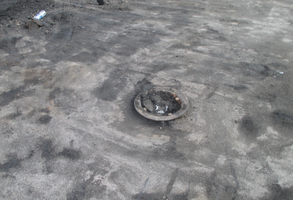
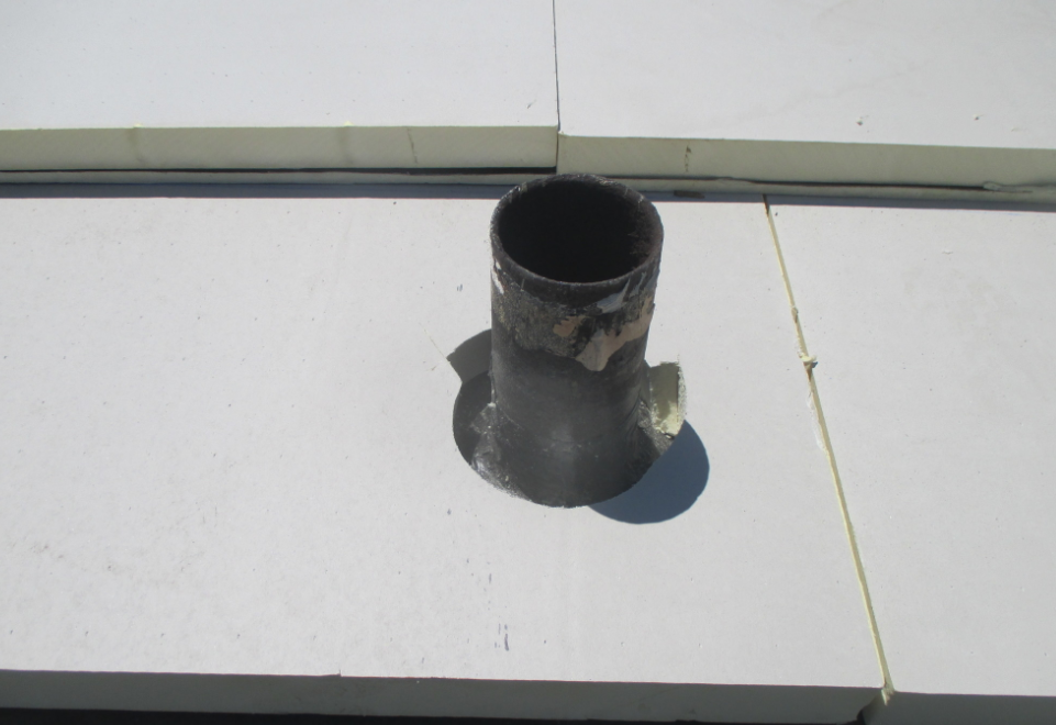
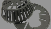
I am convinced that there is an international conspiracy to drive me nuts. It’s called the ‘how small can we cut out the membrane at the roof drain’ contest. (See Photo 3.)
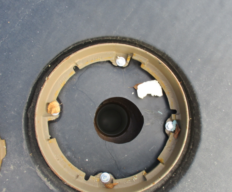
When I am called in as an expert on a building collapse, the first thing I tell the attorney is, “Save the roof drains and attached roof membrane!” Why, you ask? Because I want to see if the roofing contractor competed in the contest and if the installer and the consultant/architect will be party to the repair costs. Drains are designed to create a vortex to drain water most efficiently from the roof. (Watch how a toilet flushes to gain an understanding on how a drain works with the water swirling into the drainpipe.) The shape of the water flow from the roof surface to the drain bowl to the downspout is critical. When the hole cut in the membrane is too small, it can restrict drainage. Costs often drive projects, and it is not uncommon for a roof’s structural elements to be value engineered down to the bone. With intense rainfalls (you know, the 100-year rains that are occurring two or three times per year) and on larger roof areas where large outlet pipes are used, restricted water drainage can and has resulted in structural roof collapse.
So, I’m on a roof and observe the roofing crew cutting out a small hole at the drain. Being the conscientious consultant that I am, I ask, “Can you please cut out the membrane to within 1/2-inch of the clamping ring?” The answer is almost universal: “I’ll do it later.” Usually my blood pressure rises and face turns red as I explain the importance of making sure this detail is not overlooked.
Our details call out the proper way to cut out the membrane and our field observation reports call this out to be corrected, but I am forced to remind contractors again and again — sometimes even when it’s on the punch list. So, what’s a consultant to do? I reject the pay request.
Commandment #2: Call out on your roof drain details to cut back the membrane to within 1/2-inch of the clamping ring (a cloverleaf pattern around the bolts is best), and drive home the importance of this detail to the crew members in the field.
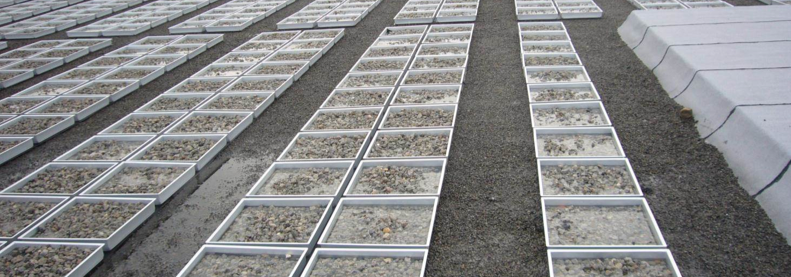
The 12-Inch Roof Curb
When energy was cheap, insulation was an inch or two in thickness, and the roof was built up, 12-inch-high roof curbs worked. With the new insulation requirements and tapered insulation, 12-inch curbs can be buried. Furthermore, future code mandates may increase insulation R-value, increasing insulation heights. So, consider this a public announcement to all mechanical engineers and curb manufacturers: Eliminate 12-inch curbs and specify curbs that are 18 inches or higher. (See Photo 4.)
Commandment #3: Specify only 18-inch and above roof curbs and rails.
Flapping in the Breeze
Driving around Chicago it’s not hard to see roof edges — gutters, gravel stop, and parapets — where the roof membrane is just flapping in the wind. (See Photos 5 and 6.) This is especially a concern when the roof system is mechanically attached and the air can move directly below the membrane. The roof typically is installed prior to the installation of the windows and doors, and while the building is open, airflow in the interior can create upward pressure on the roof system from below. This force, in association with the air getting below the membrane at the roof edge and with uplift above the membrane, drastically raises the risk of wind damage. Furthermore, when the membrane is not secured at the gutter roof edge, water draining off the roof will return back to the roof edge and move into the building and insulation.
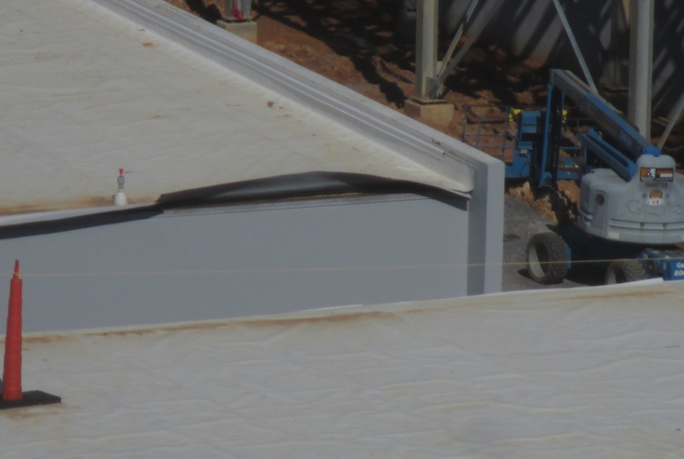
Wrap the membrane over the roof edge, adhere it in place and nail it off. This will save you during the installation and prevent air infiltration once the roof is complete. The designer should also delineate the area where the air barrier meets the roof vapor retarder and/or roof membrane and define who is responsible for what. Detail this explicitly.
Commandment #4: Roof membranes shall be extended down over the edge wood blocking a minimum of 1.5 inches onto the wall substrate, fully adhered and nailed off on the day it is installed. Where applicable, seal to the wall air barriers.
Holding Roof Drains Off the Roof Deck
Nothing is more frustrating to a roofing contractor during a re-roof than removing the old roof to install a vapor retarder and finding that the roof drain has been held up off the roof deck. (See Photo 7.) This goes back to the design when the engineer and architect have no clue as to the use of proper sump pans and roof drains with extension rings — preferably threaded.
Commandment #5: Design, detail and draw the roof drain detail showing the roof deck with a sump pan provided by the roof drain manufacturer, installed by the plumbing contractor not the guys installing the roof deck), with the roof drain now flush to the roof deck, with a reversible collar (to which the extension ring threads engage), the threaded extension ring and dome.
Fill the Void, Bury the Screw, Save the Energy
With the push over the past decade for energy savings/conservation, it is amazing to me that the code bodies have ignored two very highly energy consumptive or energy loss conditions: (1) voids in the thermal layer at penetrations and perimeter conditions; and (2) mechanical fasteners with plates below the roof cover. (See Photos 8-10.)
Some crews work to fit insulation tight to conditions. Others don’t. Eyeballing the circular cutout at vent pipes is common, resulting in fairly large voids at vent pipes. Roof edge conditions vary and significant voids can occur there, too. All of these voids need to be sealed with spray foam insulation, which should be allowed to rise and then trimmed flush to the insulation. I recommend that the spray foam be installed at each layer as subsequent insulation layers can shift the void. We have been requiring this for years without much blowback from contractors. The only issue that arose was when a contractor wanted to use polyurethane adhesive to fill voids; that was a no-go, as the polyurethane adhesive collapses down after it rises.
Mechanical fasteners used to positively secure the insulation and membrane have become commonplace. But as I’ve noted before, we have seen roofs covered in frost with hundreds, if not thousands, of little spots of melted frost. The heat transfer through the fasteners is substantial. Research has found that on a mechanically attached roof cover, the energy loss can be over 40 percent above that of a system without exposed fasteners. As energy requirements are defined by R-value and with the potential for thermal loss due to the fasteners, I propose an R-value penalty for exposed fasteners. For example, in Chicago where the R-value requirement is 30, if you have a mechanically attached roof cover, the R-value required would be 42. That way the thermal efficiency would be equivalent and building owners wouldn’t pay the price for the designer’s lack of knowledge. Thus, as the Roofing God, I would implement this penalty and require all adhered roofs to have fasteners buried below insulation or cover board layers.
Commandment # 6: Show and note on your details the installation of spray foam insulation at penetrations, roof drains and perimeters.
Commandment # 7: All mechanical fasteners should be covered with insulation or a cover board; if not, 40 percent more R-value needs to be added to the thermal layer to compensate for the energy loss.
So, there you have the new roofing commandments that I would bestow if I were the Roofing God for a day. Let’s all work together though to bring about positive change and increase the sustainability and resiliency of our roofs. Together we can do it.
About the author: Thomas W. Hutchinson, AIA, FRCI, RRC, CRP, CSI, is a principal of Hutchinson Design Group Ltd. in Barrington, Illinois. For more information, visit www.hutchinsondesigngroup.com.

Be the first to comment on "The 7 Commandments of Roofing"