

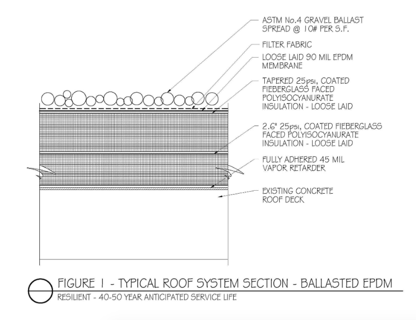
Figure 1: Designing resilient roof systems is the best of practices. When developing details, we find it very helpful to draft out the roof system (for each different system), noting materials and installation methods. Photos: Hutchinson Design Group
Single-ply membranes have risen from being the “new guy” in the market in the early ’80s to become the roof cover of choice for most architects, consultants and contractors. Material issues have for the most part been resolved, and like no other time in recent history, the industry is realizing a period of relative calm in that regard. Whether EPDM, TPO or PVC, the ease of installation, the cleanliness of the installation (versus the use of hot or cold bitumen), the speed at which they can be installed, and the material costs all blend to make these materials a viable option for watertight roofing covers. But with this market share comes issues and concerns, some of which are hurting owners, giving forensic consultants such as myself too much business, enriching attorneys, and costing contractors and, at times, designers dearly.
Following are some of my thoughts on various issues that, in my opinion, are adversely affecting single-ply membrane roof systems. Paying attention to these issues will bring about best practices in single-ply applications.
Specifying the Roof by Warranty
OMG, can architects do any less? Don’t get me started. The proliferation of “canned” Master Specs which call for a generic 10-year or 20-year warranty and then state to install the product per manufacturer’s guidelines is disheartening. Do
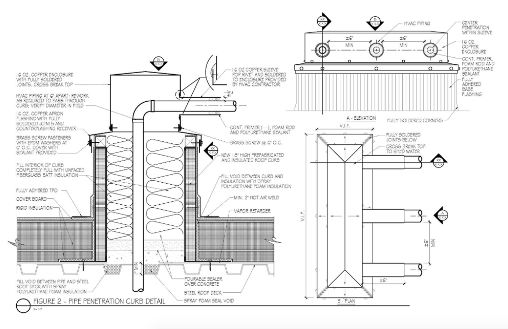
Figure 2: Coordinating with the mechanical engineer in the detailing of the pipe penetrations is critical. Here you can see all the components of the curb, penetrations, roofing and waterproofing are noted. We recommend that the same detail be on the mechanical sheets so that at least an 18-inch curb is known to all. Photos: Hutchinson Design Group
designers realize that manufacturers’ specifications are a market-driven minimum? When architects leave out key details, they are simply relying on the roofing contractor to do what is right. This deserves another OMG. The minimum requirements for a warranty can be very low, and the exclusions on a warranty quite extensive. Additionally, a design that calls for products to be installed based on achieving a warranty may result in a roof system that does not meet the code. Owners are often oblivious to the warranty requirements, and all too often fail to ensure the standard of care until the service life is shortened or there is storm damage — sometimes damage the roof should have withstood if it were properly designed and detailed.
If one is not knowledgeable about roof system design, detailing and specification, then a qualified roof consultant with proven experience in single-ply membranes should be retained. Roof systems and their integration into the impinging building elements need to be designed, detailed and specified appropriately for the building’s intended use and roof function. By way of example, we at Hutchinson Design Group typically design roof systems for a 40- to 50-year service life (see Figure 1); the warranty at that point is nice, but almost immaterial. Typical specifications, which are project specific, cover all the system components and their installation. They are typically 30 pages long and call out robust and enhanced material installations.
More Than the Code
I recently had a conversation with a senior member of a very large and prominent architectural firm in the Chicago area and inquired about how they go about designing the roof systems. The first thing he said was, “We do what is required by code.”
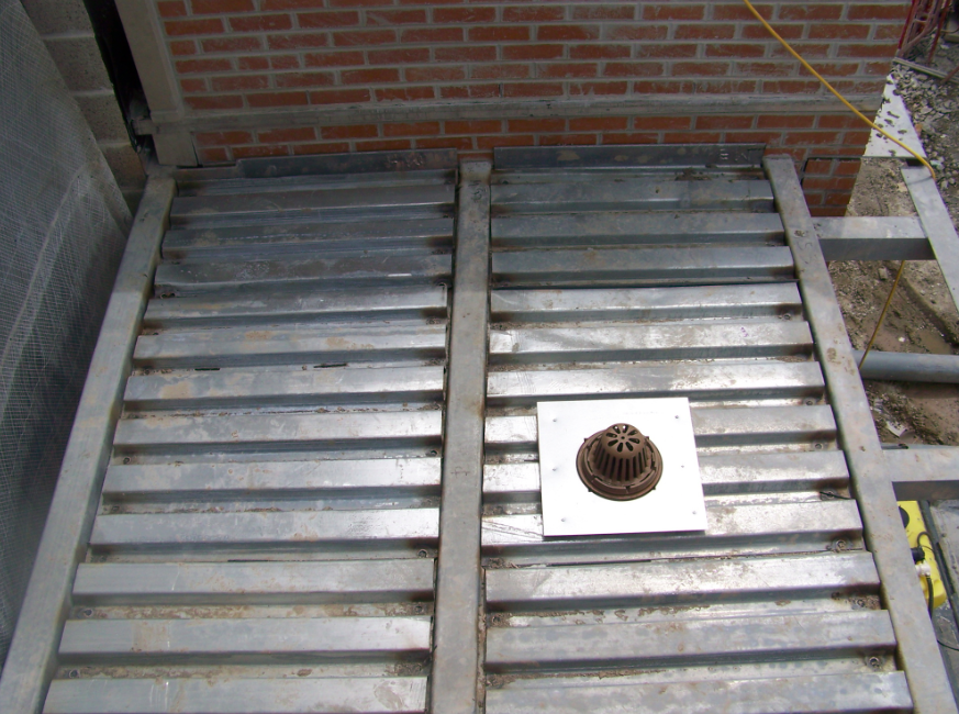
Photo 1: The roof drain sump pans shown here were provided and installed by the plumbing contractor, not the steel deck installer. Having the roof drain level with the top of the roof deck allows for a proper integration of the roof drain and roof system.
What I heard was, “We give our clients the absolute poorest roof the code allows.” An OMG is allowed here again. Does it really need to be said again that the code is a minimum standard — as some would say, the worst you are allowed to design a building by law? Maybe you didn’t realize it, but you are allowed to design above the code. I know this will shock a few of you, but yes, it’s true. Add that extra anchor to prevent wood blocking from cupping. Add extra insulation screw fasteners to improve wind uplift resistance; if too few are used, you may meet the code, but your insulation will be susceptible to cupping. Add that extra bead of polyurethane adhesive. (If I specify 4 inches on center, then perhaps by mid-day, on a hot and humid day, I might get 6 inches on center — as opposed to specifying 6 inches or 8 inches on center, and getting 12 inches on center in spots.) Plan for construction tolerances such as an uneven decks and poorly constructed walls. Allow for foot traffic by other trades. These types of enhancements come from empirical experiences — otherwise known as getting your butt in the ringer. Architects need more time on the roof to observe what goes on.
It’s About Doing What is Right
Doing it right the first time isn’t all that difficult, and it’s certainly less stressful than dealing with the aftermath of doing so little. The cost of replacing the roof in the future could easily be more than double the original cost. Twenty years ago, I
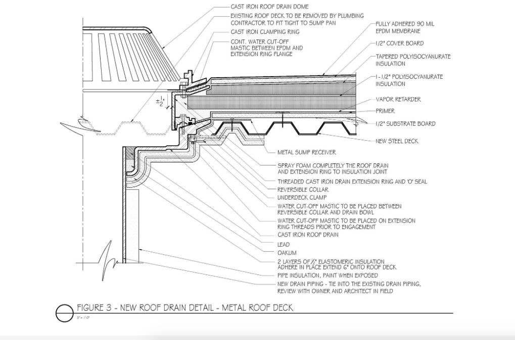
Figure 3: Coordinating with the plumbing engineer, like coordinating with the mechanical engineer, is a requirement of best practices. In this drain detail, we can see the sump pan is called out correctly, and the roof drain, integration of the vapor barrier, extension ring, etc., are clearly defined. Photos: Hutchinson Design Group
chaired an international committee on sustainable low-slope roofing. At that time, the understanding of sustainability was nil, and I believe the committee’s Tenets of Sustainability, translated into 12 languages, helped set the stage for getting designers to understand that the essence of sustainability is long-term service life. That mantra seems to have been lost as a new generation of architects is at the helm. This is unfortunate, as it comes at a time when clients no longer ask for sustainable buildings. Why? Because they are now expected. The recent rash of violent and destructive storms — hurricanes, hail, intense rain, high winds and even wildfires — have resulted in calls for improvement. That improvement is called resiliency. If you have not heard of it, you are already behind. Where sustainability calls for a building to minimize the impact of the building (roof) on the environment, resiliency requires a building (roof) to minimize the impact of the environment on the building. This concept of resiliency requires designing a roof system to weather intense storms and to be easily repaired when damaged. (Think of Puerto Rico and consider how you would repair a roof with no power, limited access to materials, and manpower that might not be able to get to your site.)
Achieving resiliency requires the roof system designer to:
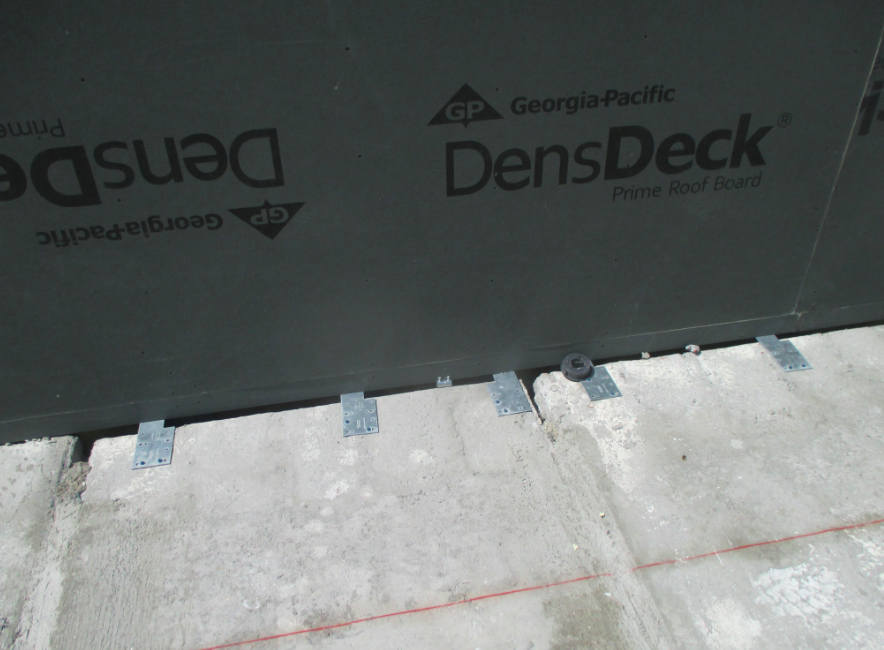
- Actually understand that roofs are systems and only as good as their weakest link. Think metal stud parapet and horizontal base anchor attachment; only forensic consultants and attorneys like to see screws into modified gypsum boards.
- Eliminate your old, out-of-date, incorrect details. Lead vent flashing and roof cement cannot be used with single-ply membrane.
- Design the roof system integration into associated barrier systems, such as where the roofing membrane (air/vapor retarder) meets the wall air barrier. You should be able to take a pencil and draw a line over the wall air barrier, up the wall and onto the roof without lifting it off the sheet. If you cannot, you need to redesign. Once you can, you need to consider constructability and who may get there first — the roofer or air barrier contractor. Then think material compatibility. Water-based air barrier systems don’t react well when hit with a solvent-based primer or adhesive.
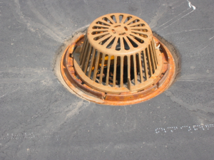
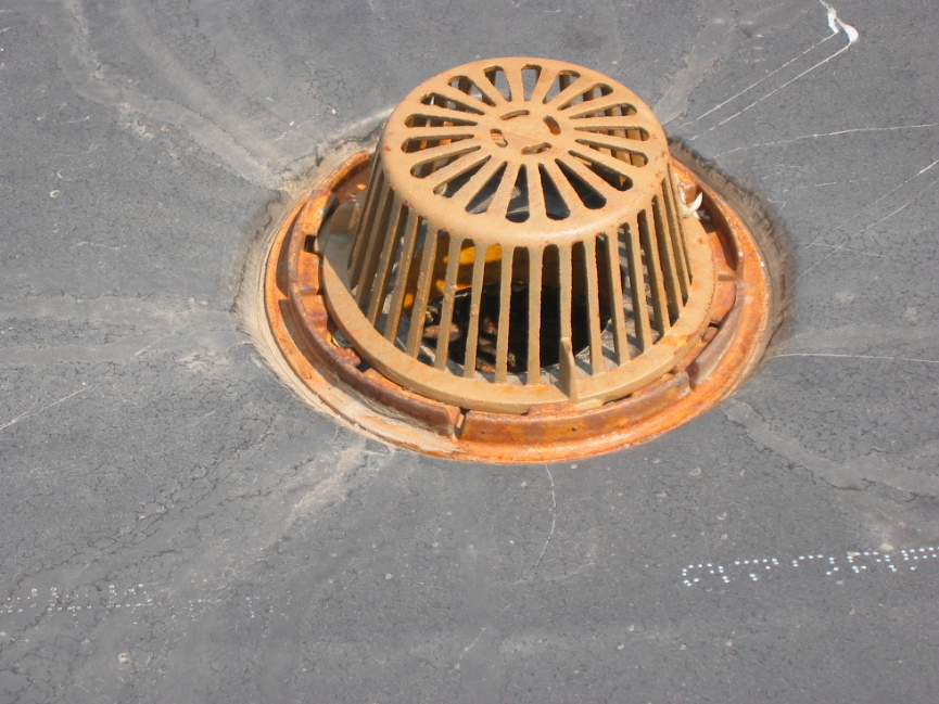
Photo 2: This roof drain is properly installed along with 6 inches of insulation and a cover board. The drain extension ring is 1/2 inch below the top of the cover board so that the water falls into the drain and is not held back by the clamping ring, resulting in ponding around the roof drain.
Perhaps the roofing needs to be in place first, and then the air barrier brought over the top of the roofing material. This might require a stainless-steel transition piece for incompatible materials. Maybe this requires a self-adhering membrane over the top of the roof edge prior to the roofing work, as some membranes are rather rigid and do not bend well over 90-degree angles. You as the designer need to design this connectivity and detail it large and bold for all to see.
- Design the roof system’s integration into the impinging building elements, including:
- Roof curbs for exhaust fans: Make sure they are insulated, of great enough height, and are not installed on wood blocking.
- Rooftop unit (RTU) curbs: The height must allow for future re-roofing. Coordinate with the mechanical engineer regarding constructability – determine when the curb should be set and when the HVAC unit will be installed. Roof details should be on both the architectural and mechanical drawings and show the same curb, drawn to scale. Be sure the curb is insulated to the roof’s required R-value. Avoid using curb rails to support mechanical equipment. The flashing on the interior side of the rails may be inaccessible once the equipment is placed. Use a large curb where all four sides will remain accessible.
- Piping penetrations: Detail mechanical piping penetrations through the roof and support of same, where insulation and waterproofed pipe curbs are needed (see Figure 2). If you are thinking pourable sealer pocket, stop reading and go sign up for RCI’s Basics of Roof Consulting course.
- Roof curbs, RTU, pipe curbs and rails: Coordinate their location and show them on the roof plan to be assured that they are not inhibiting drainage.
- Roof drains: Coordination with the plumbing engineer is essential. Sump pans should be installed by the plumbing contractor, not the steel deck installer (see Photo 1), and the location should be confirmed with the structural engineer. Be sure drains are located in the low point if the roof deck is structurally sloped — and if not, know how to design tapered insulation systems to move water up that slope. Do not hold drains off the deck to meet insulation thickness; use threaded extensions. Be sure any air/vapor barrier is integrated into the curb and that the insulation is sealed to the curb. I like to hold the drain flange a half-inch down below the insulation surface so that the clamping ring does not restrain water on the surface. Owners do not like to see a 3-foot black ring at the drain, where ponding water accumulates debris (see Figure 3 and Photo 2).
- Understand the roof’s intended use once the building is completed. Will the roof’s surface be used for anything besides weather protection? What about snow removal? Will there be excessive foot traffic? What about mechanical

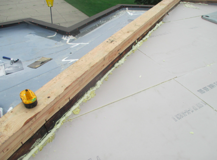
Photo 3: Gaps between the roof insulation and roof edges, curbs and penetrations are prevalent on most roofing projects and should be sealed with spray foam insulation as seen here. It will be trimmed flush once cured.
equipment? Photovoltaic panels? Yes, we have designed roofs in which a forklift had to go between penthouses across the roof. Understanding how the roof will be used will help you immensely.
- Understand the construction process and how the roof might be used during construction. It is amazing how few architects know how a building is built and understand construction sequencing and the impact it can have on a roof. I firmly believe that architects think that after a lower roof is completed, that the masons, carpenters, glazers, sheet metal workers, welders, pipe fitters, and mechanical crews take time to fully protect the newly installed systems (often of minimal thickness and, here we go again, without a cover board — OMG) before working on them. I think not. Had the architect realized that temporary/vapor retarders could be installed as work surfaces, getting the building into the dry and allowing other trades to trash that rather than the finished roof, the roof system could be installed after those trades are off the roof.
- Coordinate with other disciplines. Roof systems cannot be designed in a vacuum. The architect needs to talk to and involve the structural, mechanical and plumbing engineers to ensure they realize the importance of essential details. For example, we cannot have steel angle around the drain whose flange rests on the bar joist, thus raising the roof deck surface at the roof drain. Ever wonder why you had ponding at the drain? Now you know. I attempt to always have a comprehensive, specific roofing detail on the structural, mechanical and plumbing sheets. I give the other disciplines my details and ask that they include them on their drawings, changing notes as required. That way, my 20-inch roof curb on the roof detail is a 20-inch curb on the mechanical sheets — not a standard 12-inch curb, which would more often than not be buried in insulation.
- Detail, detail, detail, and in case you glossed over this section, detail again. Make sure to include job-specific, clearly drawn details. Every condition of the roof should be detailed by the architect. Isn’t that what the client is paying for? Do not, as I once saw, indicate “RFO” on the drawings. Yes, that acronym stands for “Roofer Figure Out.” Apparently, the roofer did not figure it out. I enjoyed a nice Hawaiian vacation as a result of my work on that project, courtesy of the architect’s insurance company. How do you know that a condition works unless you design it and then draw it to scale?
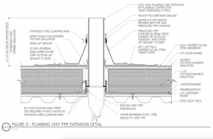
Figure 4: Insulation to curbs, roof edge and penetrations will not be tight, and to prevent a thermal short, the gaps created in construction need to filled with spray foam, as noted and shown here in this vent detail. Photos: Hutchinson Design Group
I’ve seen roof insulation several inches above the roof edge because, OMG, the architect wanted gravel stop and forgot about camber. Not too big a deal (unless of course it’s a large building) to add several more layers of wood blocking and tapered edge strips at the now high wood blocking in the areas that were flush, but now the face of the roof edge sheet metal needs to increase. But what if the increase is above the allowable ANSI-SPRI ES1 standard and now a fascia and clip are required? You can see how the cost spirals, and the discussion ensues about who pays for what when there is a design error.
- Develop comprehensive specifications that indicate how the roof system components are to be installed. This requires empirical knowledge, the result of time on the roof observing construction. It is a very important educational tool that can prevent you, the designer, from looking like a fool.

Components
Best practices for single-ply membranes, in addition to the design elements above, also involve the system components. Below is a listing of items I feel embodies best practices for single-ply roof system components:
- Thicker membranes: The 45-mil membrane is insufficient for best practices, especially when one considers the thickness of the waterproofing over scrim on reinforced sheets. A 60-mil membrane is in my opinion the best practices minimum. Hear that? It’s the minimum. You are allowed to go to 75, 80 or 90 mils.
- Cover boards: A cover board should be specified in fully adhered and mechanically attached systems. (Ballasted systems should not incorporate a cover board.) Cover boards have enhanced adhesion of the membrane to the substrate over insulation facers and hold up better under wind load and hail. Cover boards also protect the insulation
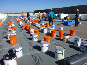
Photo 4: The greatest concern with the use of polyurethane adhesives is that the insulation board might not be not fully embedded into the adhesive. Weighting the boards at the corners and center with a minimum of 35 pounds for 10 minutes has proven to work well in achieving a solid bond.
from physical damage and remain robust under foot traffic, while insulation tends to become crushed. Cover boards are dominated by the use of mat-faced modified gypsum products. Hydroscopic cover boards such as fiberboards are not recommended.
- Insulation: Now here is a product that designers seldom realize has many parts to be considered. First, let’s look at compression strength. If you are looking to best practices, 25 psi minimum is the way to go. The 18-psi insulation products with a fiber reinforced paper facer can be ruled out entirely, while 20 psi products are OK for ballasted systems. Now let’s look at facers. If you think about it for a second, when I say “paper-faced insulation,” you should first think “moisture absorbing” and secondly “mold growth.” Thus paper-faced products are not recommended to be incorporated if you are using best practices. You should be specifying the coated glass-faced products, which are resistant to moisture and mold resistant. A note to the manufacturers: get your acts together and be able to provide this product in a timely manner.

Additional considerations regarding insulation:
- Insulation joints and gaps: You just can’t leave joints and gaps open. Show filling the open joints at the perimeter and curbs and around penetrations with spray foam in your details and specify this as well (see Photo 3 and Figure 4).
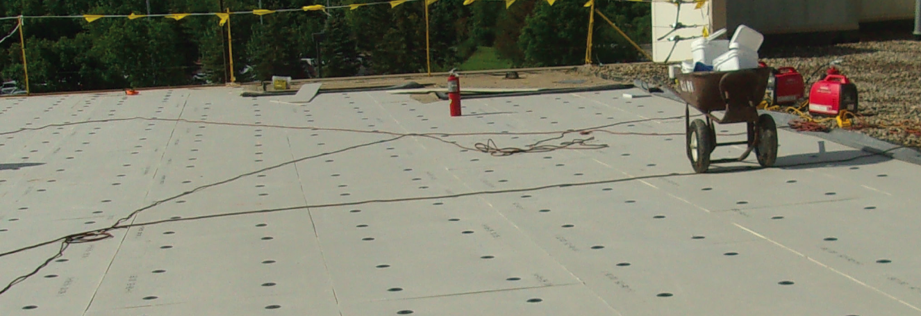
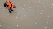
- Mechanical attachment: Define the method of attachment and keep it simple. On typical projects, I commonly specify one mechanical fastener every 2 square feet over the entire roof (unless more fasteners are needed in the corners). Reducing the number of fasteners in the field compared to the perimeter can be confusing for contractors and the quality assurance observer, especially when the architect doesn’t define where that line is. The cost of the additional screws is nominal compared with the overall cost of the roof.
- Polyurethane foam adhesive: Full cover spray foam or bead foam adhesive is taking over for asphalt, at least here in the Midwest, and I suspect in other local markets as well. The foam adhesive is great. It sticks to everything: cars, skylights, clerestories, your sunglasses. So, it is amazing how many insulation boards go down and don’t touch the foam. You must specify that the boards need to be set into place, walked on and then weighted in place until set. We specify five 35-pound weights (a 5-gallon pail filled with water works nicely), one at each corner and one in the middle for 10 minutes (see Photo 4). Yes, you need to be that specific.
-

Photo 5: The design of exterior walls with metal studs that project above the roof deck is a multi-faceted, high-risk detail that is often poorly executed. Here you can see a gap between the deck and wall through which warm moist air will move and result in the premature failure of this roof. The sheathing on the wall cannot hold the horizontal base anchor screw, and the joints in the board allow air to pass to the base flashing, where is will condense. This is the type of architectural design that keeps on giving — giving me future work.
Vapor/air barrier: A vapor air barrier can certainly serve more than a function as required for, say, over wet room conditions: pools, locker rooms, kitchens, gymnasiums. We incorporate them in both new construction and re-roofing as a means of addressing construction trade phasing and, for re-roofing, allowing time for the proper modification of existing elements such as roof edges, curbs, vents, drains, skylights and pipe curbs. Be sure to detail the penetrations and tie-ins with wall components.
- Deck type: Robust roof decks are best. Specify 80 ksi steel roof decks. Try staying away from joint spacing over 5 feet. Decks should be fully supported and extend completely to roof edges and curbs.
- Roof edge design: A key aesthetic concern, the termination point for the roof system, the first line of defense in regard to wind safety — the roof edge is all of these. The construction of the roof edge on typical commercial construction has changed drastically in the last 20 years, from brick and block to metal stud. Poorly designed metal stud parapets will be funding my grandkids’ college education. The challenge for the metal stud design is multifaceted: It must close off the chimney effect, prevent warm moist air from rising and condensing on the steel and wall substrate, create an acceptable substrate on the stud face in which to accept base anchor attachment, and — oh, yes — let’s not forget fire issues. Tread lightly here and create a “big stick” design (see Photo 5).
- Roof drains and curbs: As discussed above, there is a great need for coordination and specific detailing here. The rewards will be substantial in regard to quality and efficiency, minimizing time spent dealing with “what do we do now” scenarios.
- Slope: Design new structures with structural roof deck slope, then fine tune with tapered insulation.
Final Thoughts
Best practices will always be a balancing act between cost and quality. I believe in the mantra of “doing it right the first time.”
The industry has the material and contractors possess the skill. It’s the design and graphic communication arm that needs to improve to keep everyone working at the top of their game.
Designers, get out in the field and see the results of your details. See firsthand how a gypsum-based substrate board on a stud wall does not hold screws well; how a lap joint may not seal over the leading edge of tapered insulation; how the roof either ponds water at the roof drain or doesn’t meet code by drastically sumping; or how the hole cut in the roof membrane for the drain might be smaller than the drain bowl flange, thus restricting drainage. Seeing issues that the contractors deal with will help you as the designer in developing better details.
Contractors, when you see a detail that doesn’t work during the bidding, send in an RFI and not only ask a question, but take the time to inform the architect why you don’t think it will work. On a recent project here in Chicago, the architect omitted the vapor retarder over a pool. The contractor wrote an explicit explanation letter and RFI to the architect during bidding, and the architect replied, “install as designed.” In these situations, just walk away. For me, this is future work. A local contractor once told me, “I don’t get paid to RFI, I get paid to change order.” He also said, “If I ever received a response to an RFI, I would frame it!”
Manufacturers, too, can raise the bar. How about prohibiting loose base flashings at all times, and not allowing it when the salesman says the competition is allowing it. Have contractors on the cusp of quality? Decertify them. You don’t need the hassles. Owners don’t need the risk.
Seek out and welcome collaboration among contractors, roof systems designers, knowledgeable roof consultants, and engineers. Learning is a lifelong process, and the bar is changing every year. Too often we can be closed off and choose not to listen. At HDG, I am proud to say we have the building owners’ best interests at heart.
By all working together, the future of single-ply membranes can be enhanced and the systems will be retained when the next generation of roof cover arrives — and you know it will.


Be the first to comment on "Single-Ply Roofing Best Practices: Doing Everything Right the First Time."