
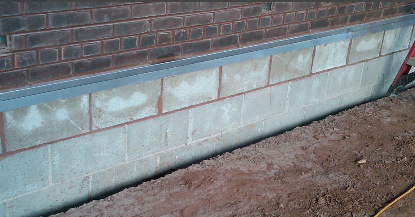
PHOTO 1: The through-wall flashing stainless-steel drip can be observed projecting nicely from the wall—but the termination of the roof base flashing more than 1-inch below resulted in a section of the brick wall that allows water to pass into the wall below the through-wall flashing and behind the roof base flashing, resulting in the damage seen in Photo 2.
“What a genius! His spatial conception is magnificent, even after 100 years.”
“But all his buildings leak!”
I used to give a talk to University of Illinois architecture students in which I told them the quickest way to go out of business is to be sued. The quickest way to be sued is to have a building allow moisture intrusion. If he were alive today, Frank Lloyd Wright—God rest his soul—would be in jail (and a few current architects may be well on their way). Owners are not very kind when their “babies” leak.
Many roof termination interfaces are never even thought about by designers and are left to the roofing contractor to work out. This is not a recommended practice. One such condition—that every architect should be able to detail—is how the roof base flashing terminates at a masonry wall that has through-wall flashing and weeps at the base of the wall above the roof. I believe so fervently that architects should be proficient in detailing these conditions that I believe it should be required to procure their license.
WHY THE IMPORTANCE
The interface of roof base flashing and masonry through-wall systems occurs on a majority of commercial construction projects. If this transition is not performed correctly, moisture intrusion behind the roof base flashing to the interior will occur (see Photo 2). When this occurs, besides angering owners, it befuddles the architect. Photo 1 (left) shows a nice through-wall flashing drip extended out from the wall, weeps and roofing terminated with a termination bar and sealant. What could be wrong?
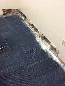
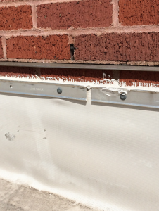
PHOTO 2: Moisture intrusion at the base of this wall was the result of water circumventing the through-wall flashing
and roof base flashing termination seen in Photo 1. A big concern with conditions, such as this, is the propensity of the materials to promote mold growth.
The exposed brick above the termination bar and below the stain- less-steel drip of the through-wall flashing is susceptible to water flowing down the surface of the brick. Water passing through the brick above is supposed to be weeped out; however, at the exposed brick above the termination bar, the water moves into the wall and has nowhere to go but inward.
The cost to repair these conditions can be, depending on the conditions, expensive. Repairs often require brick removal and through-wall flashing mitigation. In this particular case, be- cause there is a stainless-steel drip, my team recommended a stainless-steel counterflashing be pop-riveted to the drip and extended over the termination bar.
CHALLENGES
Why is the interface of roof base flashing and masonry through-wall systems so difficult for architects and roof consultants to detail? I believe it is because they have no clue it needs to be detailed as an interface, especially because detailing of appropriate through-wall systems is so sporadic. I endeavor in this article to change at least the knowledge part.
The detailing of this condition not only requires the ability to interface two building systems, but also requires considerable time to ensure specification of wall sectional details and roofing details are appropriately placed where the responsible trades will see them.
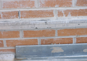
PHOTO 3: Still under construction, the stainless-steel counterflashing has
been installed. The roof base flashing will terminate below the stainless-steel counterflashing receiver. Hutch prefers brick below the through-wall flashing and above the roof deck, though the masonry mortar joints below the through-wall flashing should have been struck flush.
NEW CONSTRUCTION
New construction provides us a clean slate to “do it right the first time”. The first order of business is to determine the height of the base flashing. This can be tricky with tapered insulation and slope structures with saddles. Let’s consider the following examples (see Detail 4, page 3):
EXAMPLE 1
We are dealing with a flat roof, tapered insulation, cover board and bead-foam insulation in ASHRAE Climate Zone 5, which has an R-30 minimum.
- The roof drain is 32-feet away from the wall. Code requires 5.2 inches of insulation at 4 feet from the drain, so let’s assume 5 inches at the drain.
- 1/4-inch tapered starts at 1/2 inch at 32 feet. That’s 8 inches, plus the starting thickness of 1/2 inch, which equals 8 1/2 inches.
- Cover-board thickness is 1/2 inch.
- Bead foam thickness is 3/16 inch for each layer. Let’s assume five layers, so 1 foot of bead foam.
Thus, the surface of the roof at the wall will be 15 inches above the roof deck.
Because you would like to work at the masonry coursing level and given that concrete masonry units (CMU) are nominal 8 inches, you are looking at placing the through-wall flashing 24 inches above the roof deck.
This 24-inch dimension of where to place the through-wall flashing needs to be placed on the building section and/or wall section because the mason, which will be onsite prior to the roofing contractor, will need to know this information.
This 24-inch height begs another termination question: What occurs at the roof edge with this height? Hold that thought for now. Terminations at intersections will be discussed in future articles.
Be the first to comment on "The Integration of Roof and Brick Requires Concise Details"