
The Resilient Parapet Roof Edge
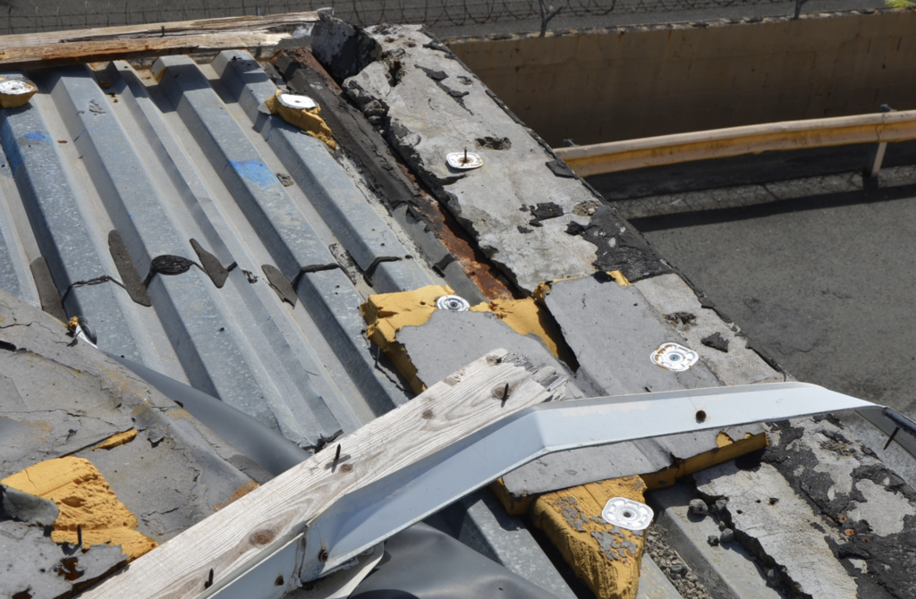
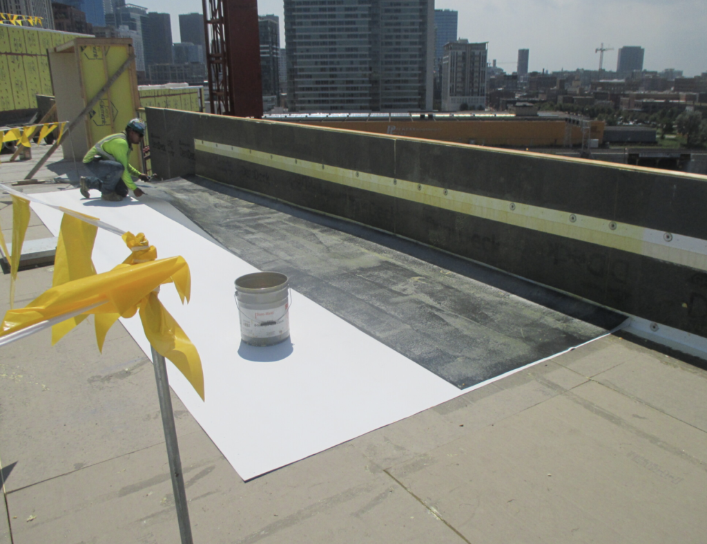
Experts cite — and codes and standards reflect — that most roof damage done by winds starts at the roof edge. From coping blow-offs, which often take the wood blocking on top the parapet wall with it, to removal of the membrane and more, evidence shows the roof edge is a key element in attaining a high-performance, resilient roof edge. (See Photo 1.)
When I was president of RCI (now IIBEC), Reid Ribble was the president of NRCA (he is now its CEO). He and I felt that the parapet was the way to go in regard to providing safety on the roof for roofing crews, HVAC crews, and maintenance crews alike. Great idea, right? You won’t believe the fight we received, and you wouldn’t believe the greatest argument came from the firefighters who might have to drop over a 42-inch parapet. When was the last time you saw a fire where the firefighters accessed the roof? I only see them pouring water on it from a hose from a lift. But I digress. Despite this argument, more and more parapets are gaining height.
What Makes a Parapet Resilient?
A parapet whose height deflects some of the straight-line winds is a great start. For our discussion, let’s start by defining what we mean by parapet: roof edge, part of the perimeter exterior wall system that extends above the roof. For this article, we will concern ourselves with those rising to a height of 30 inches or more above the roof, where the roof membrane/base flashing extends up and over the top of the parapet.
Well, since we are talking roofing, it’s the combination of parapet wall construction and the integration of the roof cover that is crucial. Let’s take a quick look at what the parameters might be. Types of parapet construction include:
· Precast panels
· Brick – concrete masonry units
· Brick on structural metal studs (Egh — I hate this type of construction.)
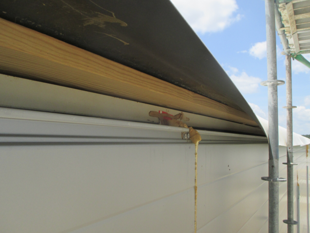
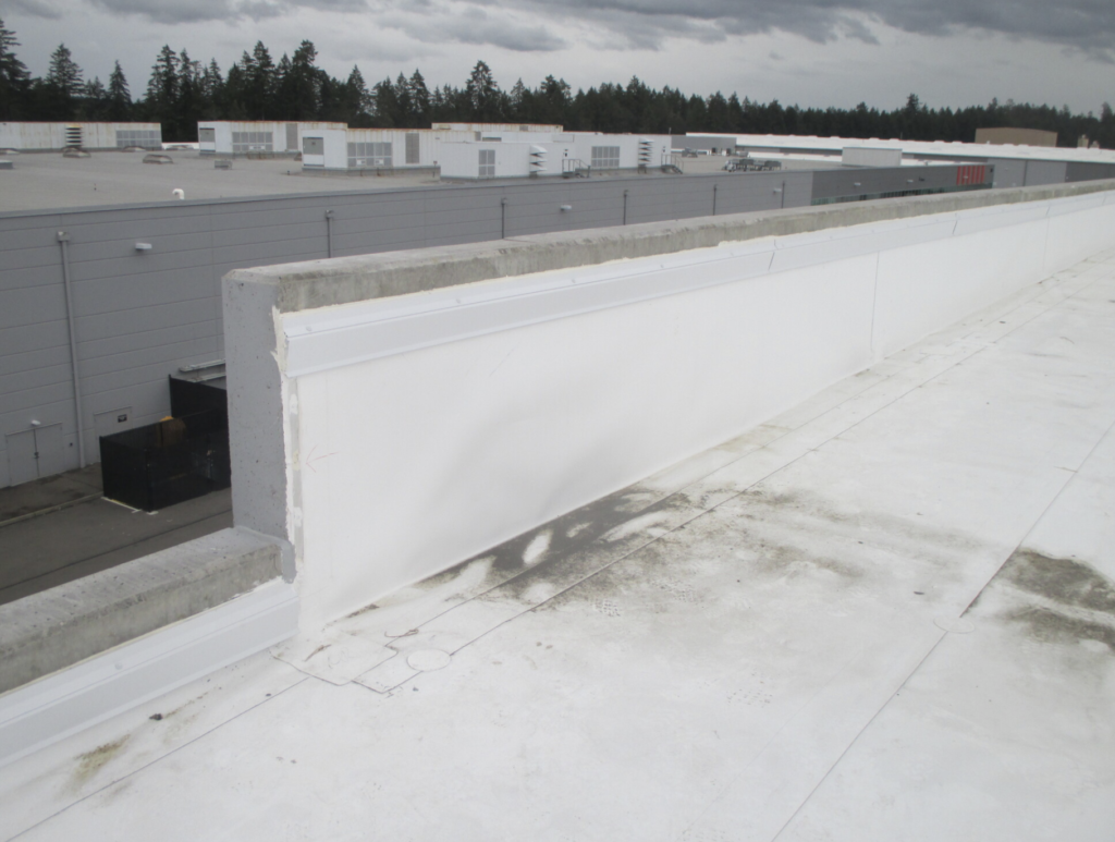
· Metal panels on structural metal studs (Egh — see Photo 2. Point proven.)
· Anything on structural metal studs (Egh.)
The parapet height places several outward forces on the roofing (base flashing) that are not experienced by lower roof edges, and thus certain enhancements need to be considered:
· Proper substrate. (OK you roofers, how often do you see a wall substrate board specified where membrane will be adhered?)
· For metal stud walls, heavy gauge metal plate to secure the roof base anchor attachment. (See The Hutchinson Files article “The Stud Wall and the Roof” in the January/February 2019 issue of Roofing.)
· Stoppage of air transport into the parapet construction. (This topic requires its own article on the requirements and detailing.)
· Proper anchorage of any wood blocking on top of the parapet.
· Enhanced membrane anchorage.
· Membrane peel stops.
· Mid-wall securement: wall peel stops.
· Base flashing that extends up and over the parapet and adheres to the exterior cladding. (Under no circumstances should the base flashing be installed loose; it must always be adhered.)
· And for those designers out there, a positive securement of the air barrier to the roof vapor barrier or membrane.
· ANSI-ES1-compliant copings
These enhancements will also protect delaminating base flashing from pulling off the parapet wall and taking with it the roof cover. This condition is the result of poor roof edge design, air transport and condensation.
Detail Drawings
The resilient parapet should incorporate several enhancements and be specifically detailed and specified. Shop drawings and mockups are required.
Below are five examples of the types of enhancements that I suggest would help make the parapet more resilient. Details that I suggest being incorporated into the drawings include:
1. Wood Blocking atop the parapet: If wood is incorporated atop the parapet (and it’s nice if you can detail it without it), it needs to be adequately anchored to the building structure. Nails are never used, and drive-in and Tapcon anchors are not sufficient. For masonry walls and pre-cast walls, I suggest expansion anchors. I like them at least at 2 feet on center (O.C.), staggered to prevent warping. Atop structural metal stud walls, first the top plate needs to be secured, the wood installed with self-tapping screws at 1 foot O.C. and then the wood blocking strapped to the studs with heavy-gauge metal —20 gauge or heavier. Joints should be scarfed at 45 degrees and screwed. If a second layer of wood is required, shim it for taper to the interior and secure with coated wood screws at 1 foot O.C. staggered, and stagger the joints. The strapping then would go over both layers.
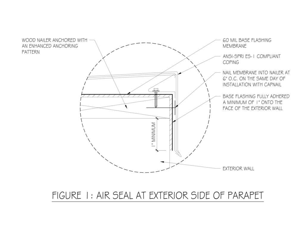
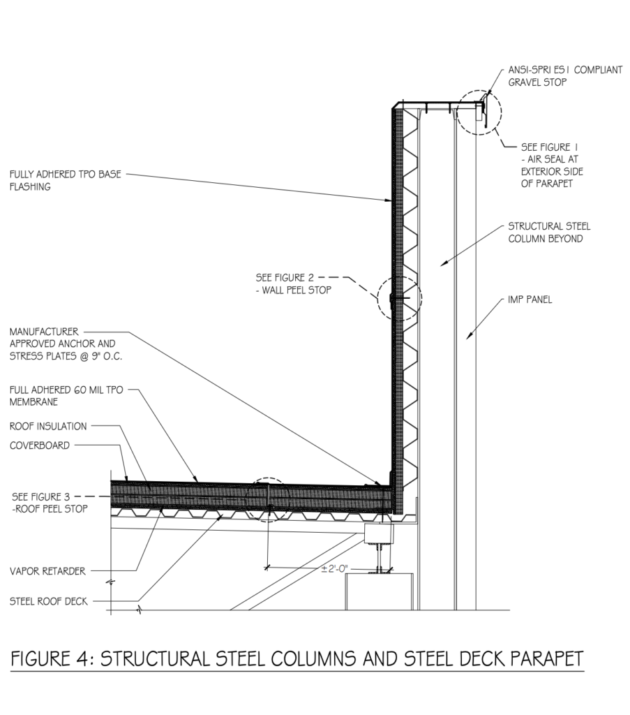
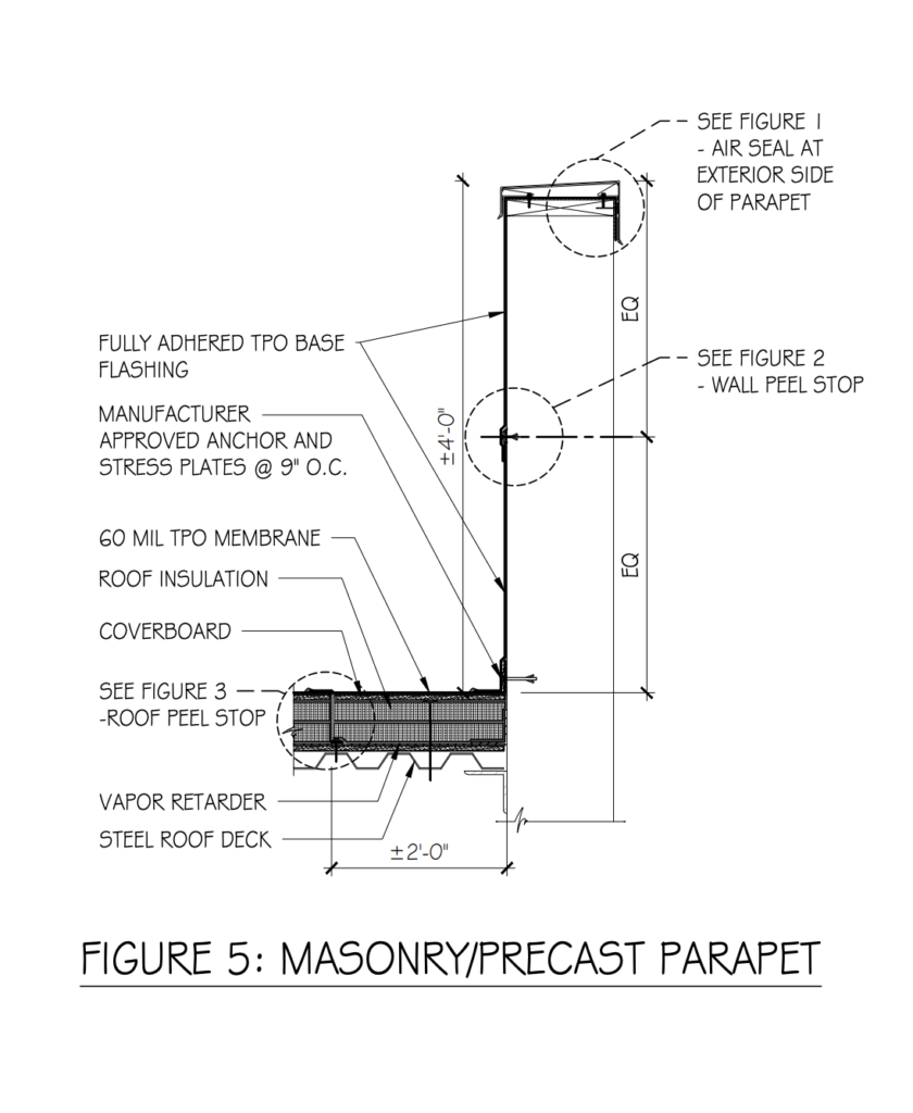
2. Seal the membrane to the exterior edge: The roof base flashing should be extended up and over the parapet, fully adhered to both the back and top of the parapet, down and onto the face of the exterior wall. It should be adhered and nailed. (See Photo 2 and Figure 1.)
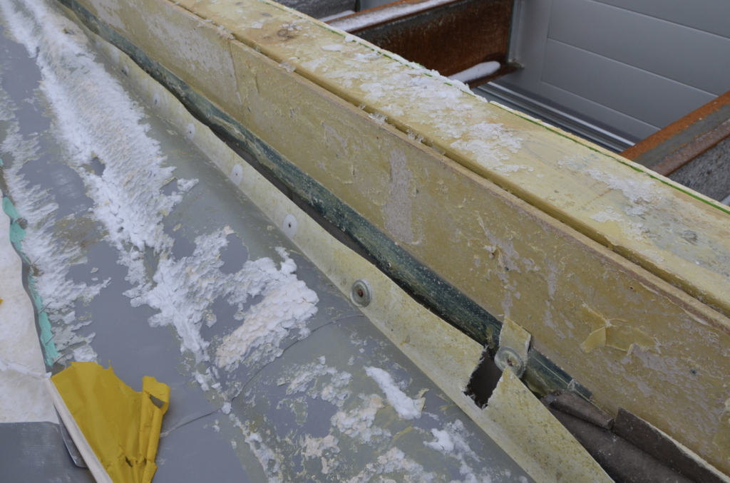
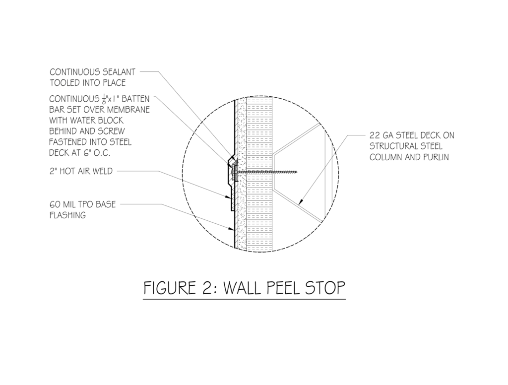
3. Wall peel stop: Due to a variety of issues (lack of air seal, condensation, inadequate adhesive application, weight of the material, and air pressure, to name a few), the base flashing can delaminate. Delaminated base flashing create a condition that I like to refer to as “pulling tape off the floor.” With each flutter of the membrane, a little bit more is detached until the force is great enough to pull the membrane anchorage out of the plates through the membrane. Thus, a wall peel stop is required: A batten bar installed on the wall and flashed in. The location of the batten bar is dependent on the parapet height and construction; I like to start out with the mid-point and no more than 3 feet from the coping and the base anchor. (See Photos 3-5 and Figure 2 for an example of a wall peel stop.)
4. Enhanced membrane base anchorage: Manufacturers (whose requirements are often market-driven minimums) require a base anchor (for single plies) of 12 inches O.C. Not good enough. We enhance that spacing to 6 inches or 9 inches O.C., depending on the location. Very seldom do we specify 12 inches. (See Figure 2.)
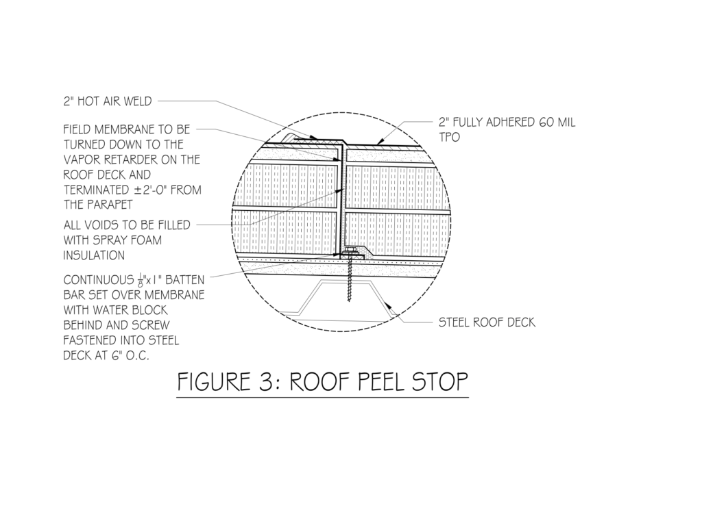
5. Roof peel stop: Like the wall peel stop, I suggest a roof peel stop so that in the chance that the roof cover detaches, only a small portion of the perimeter is in jeopardy. This peel stop should be located along the perimeters. Depending on the construction, I like to locate them every 2 feet (half an insulation board). The insulation is stopped at this location and the membrane taken down to the vapor retarder/roof deck, sealed with water block, and anchored with a batten bar and screw fasteners. The remaining insulation is then set, the void spray foamed with insulation, and the new membrane taken over and adhered/welded to the main roof cover. (See Figure 3.)
Included here are several examples of enhanced and resilient parapet roof edge detailing. (See Figures 4 and 5.) Showing the detail in depth or by exploded location will help you as the designer to know what is going on and will communicate to the contractor what is required. While the design of roof edge parapets will more often than not be different from project to project, I hope the concepts here provide the impetus for enhanced detailing.
It All Starts at the Edge
Resilient roof system design is needed for our clients, whether they know it or not. The survival of the roof system during enhanced climatic events starts at the roof edge, and thoughtful design and detailing of the parapet will help protect the roof — and help you sleep at night.
About the author: Thomas W. Hutchinson, AIA, CSI, Fellow-IIBEC, RRC, is a principal of Hutchinson Design Group Ltd. in Barrington, Illinois. For more information, visit www.hutchinsondesigngroup.com.


Be the first to comment on "Detailing for Resilience, Part 3"