

“Energy efficiency,” “energy conservation,” and “reduction of energy use” are terms that are often used interchangeably, but do they mean the same thing? Let’s look at some definitions courtesy of Messrs. Merriam and Webster, along with my interpretation and comment:
· Energy efficiency: Preventing the wasteful use of a particular resource. (Funny thing, though — when you type in “energy efficiency” in search engines, you sometimes get the definition for “energy conservation.”
· Energy conservation: The total energy of an isolated system remains constant irrespective of whatever internal changes may take place, with energy disappearing in one form reappearing in another. (Think internal condensation due to air leaking, reducing thermal R-value of the system.)
· Reduction: The action of making a specific item (in this case energy use) smaller or less in amount. (Think cost savings.)
· Conservation: Prevention of the wasteful use of a resource.
So, looking at this article’s title, what does “designing a thermally efficient roof system” imply?
I conducted an informal survey of architects, building managers, roof consultants and building owners in Chicago, and they revealed that the goals of a thermally efficient roof system include:
- Ensuring energy efficiency, thus preventing the wasteful use of energy.
- Reducing energy use, thus conserving a resource.
- Being energy conservative so that outside forces do not reduce the energy-saving capabilities of the roof system.
Unfortunately, I would hazard a guess and say that most new roof systems being designed do not achieve energy conservation.
Why is this important? The past decade has seen the world building committee strive to ensure the energy efficiency of our built environment.
A building’s roof is often the most effective part of the envelope in conserving energy. The roof system, if designed properly, can mitigate energy loss or gain and allow the building’s mechanical systems to function properly for occupant comfort.
Energy conservation is increasingly being viewed as an important performance objective for governmental, educational, commercial and industrial construction. Interest in the conservation of energy is high and is being actively discussed at all levels of the building industry, including federal and local governments; bodies that govern codes and standards; and trade organizations.
As with many systems, it is the details that are the difference between success and failure on the roof. This article will be based on the author’s 35 years of roof system design and in-field empirical experience and will review key design elements in the detailing of energy-conserving roof systems. Best design and detail practices for roofing to achieve energy conservation will be delineated, in-field examples reviewed and details provided.
Advocacy for Improvement
In the past decade, American codes and standard associations have increased the required thermal values every updating cycle. They have realized the importance of energy conservation and the value of an effective thermal layer at the roof plane. They have done this by prescribing thermal R-values by various climatic zones defined by the American Society of Heating and Air-Conditioning Engineers, now better known by its acronym ASHRAE. Additionally, two layers of insulation with offset joints are now prescribed in the IECC (International Energy Conservation Code). Furthermore, the American Institute of Architects (AIA) has also realized the importance of conserving energy and defined an energy conservation goal called the 2030 Challenge, in which they challenge architects, owners and builders to achieve “zero energy” consuming buildings by 2030.
These codes, standards and laudable goals have gone a long way to improving energy conservation, but they are short on the details that are needed to achieve the vision.
Energy Conservation Is More Than Insulation
Roofs are systems and act as a whole. Thus, a holistic view of the system needs to be undertaken to achieve a greater good. Roof system parameters such as the following need to be considered:
- Air and/or vapor barriers and their transitions at walls, penetrations and various roof edges.
- Multiple layers of insulation with offset joints.
- Preventing open voids in the thermal layers at perimeters and penetrations.
- Protection of the thermal layer from physical damage above and warm moist air from below.
Air intrusion into the roof system from the interior can have extremely detrimental consequences. In fact, Oak Ridge National Laboratory research has found that air leakage is the most important aspect in reducing energy consumption. Interior air is most often conditioned, and when it moves into a roof system, especially in the northern two-thirds of the country where the potential for condensation exists, the results can include wet insulation, deteriorating insulation facers, mold growth and rendering the roof system vulnerable to wind uplift. Preventing air intrusion into the roof system from the interior of the building needs to be considered in the design when energy efficiency is a goal. Thus, vapor retarders should be considered for many reasons, as they add quality and resiliency to the roof system (refer to my September/October 2014 Roofing article, “Vapor Retarders: You Must Prevent Air and Vapor Transport from a Building’s Interior into the Roof System”). The transition of the roof vapor/air barrier and the wall air barrier should be detailed and the contractors responsible for sealing and terminations noted on the details.
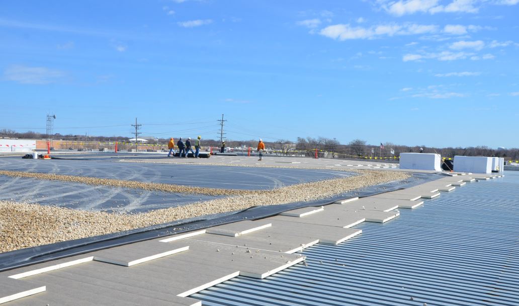
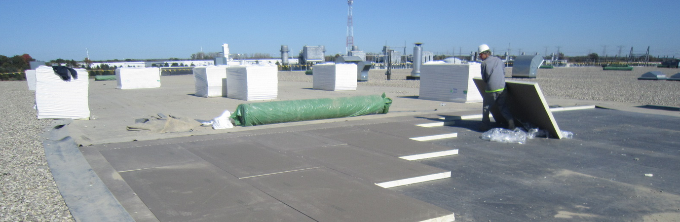
One layer of insulation results in joints that are often open or could open over time, allowing heat to move from the interior to the exterior — a thermal short. Energy high to energy low is a law of physics that can be severe. Thus, the International Code Council now prescribes two layers of insulation with offset joints. (See Photo 1.)
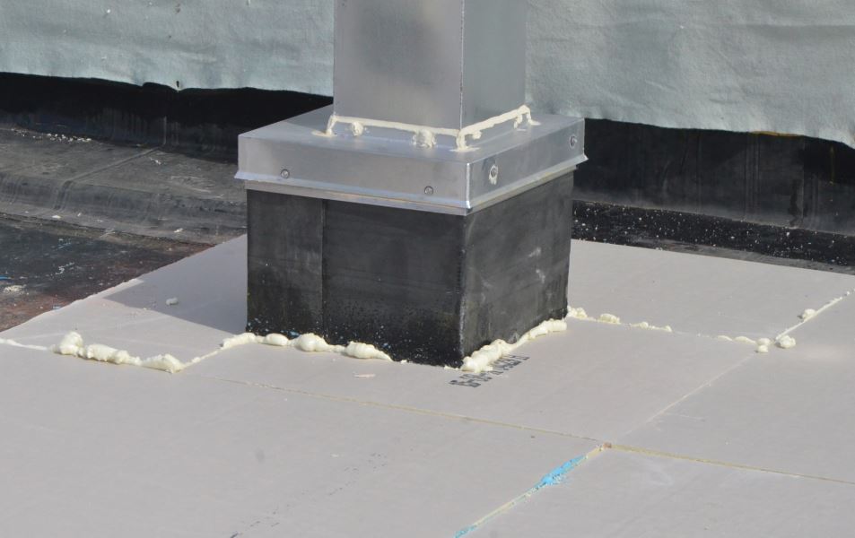
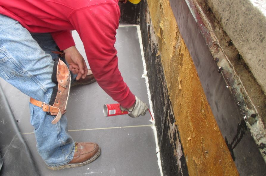
When rigid insulation is cut to conform around penetrations, roof edges and rooftop items, the cuts in the insulation are often rough. This results in voids, often from the top surface of the roof down to the roof deck. With the penetration at the roof deck also being rough, heat loss can be substantial. Thus, we specify and require that these gaps be filled with spray foam insulation. (See Photos 2 and 3.)
Insulation Material Characteristics and Energy Conservation
In addition to the system components’ influence on energy loss, the insulation material characteristics should also be considered. The main insulation type in the United States is polyisocyanurate. Specifiers need to know the various material characteristics in order to specify the correct material. Characteristics to consider are:
- Density: 18, 20, 22 or 25 psi; nominal or minimum.
- Facer type: Fiber reinforced paper or coated fiberglass.
- Dimensional stability: Will the material change with influences from moisture, heat or foot traffic.
- Thermal R-value.
In Europe, a popular insulation is mineral wool, which is high in fire resistance, but as with polyisocyanurate, knowledge of physical characteristic is required:
- Density: If you don’t specify the density of the insulation board, you get 18 psi nominal. Options include 18, 20 and 25 psi; the higher number is more dimensionally stable. We specify 25 psi minimum.
- Protection required: Cover board or integral cover board.
- Thermal R-value.
Protecting the Thermal Layer
It is not uncommon for unknowledgeable roof system designers or builders looking to reduce costs to omit or remove the cover board. The cover board, in addition to providing an enhanced surface for the roof cover adhesion, provides a protective layer on the top of the insulation, preventing physical damage to the insulation from construction activities, owner foot traffic and acts of God.
The underside of the thermal layers should be protected as well from the effects of interior building air infiltration. An effective air barrier or vapor retarder, in which all the penetrations, terminations, transitions and material laps are detailed and sealed, performs this feat. If a fire rating is required, the use of gypsum and gypsum-based boards on roof decks such as steel, wood, cementitious wood fiber can help achieve the rating required.
Insulation Attachment and Energy Efficiency
The method in which the insulation is attached to the roof deck can influence the energy-saving potential of the roof system in a major way. This fact is just not acknowledged, as I see some mechanically attached systems being described as energy efficient when they are far from it. Attaching the insulation with asphalt and/or full cover spray polyurethane adhesive can — when properly installed — provide a nearly monolithic thermal layer from roof deck to roof membrane as intended by the codes.

Another very popular method of attaching insulation to the roof deck and each other is the use of bead polyurethane foam adhesive. The beads are typically applied at 6 inches (15.24 cm), 8 inches (20.32 cm), 9 inches (22.86 cm) or 12 inches (30.48 cm).
The insulation needs to be compressed into the beads and weighted to ensure the board does not rise up off the foam. Even when well compressed and installed, there will be a ±3/16-inch void between the compressed beads, as full compression of the adhesive is not possible. This void allows air transport, which can be very detrimental if the air is laden with moisture in cold regions. The linear void below the insulation also interrupts the vertical thermal insulation section.
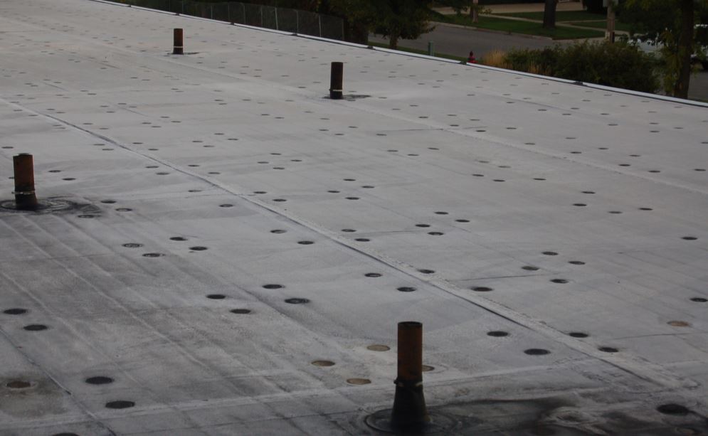
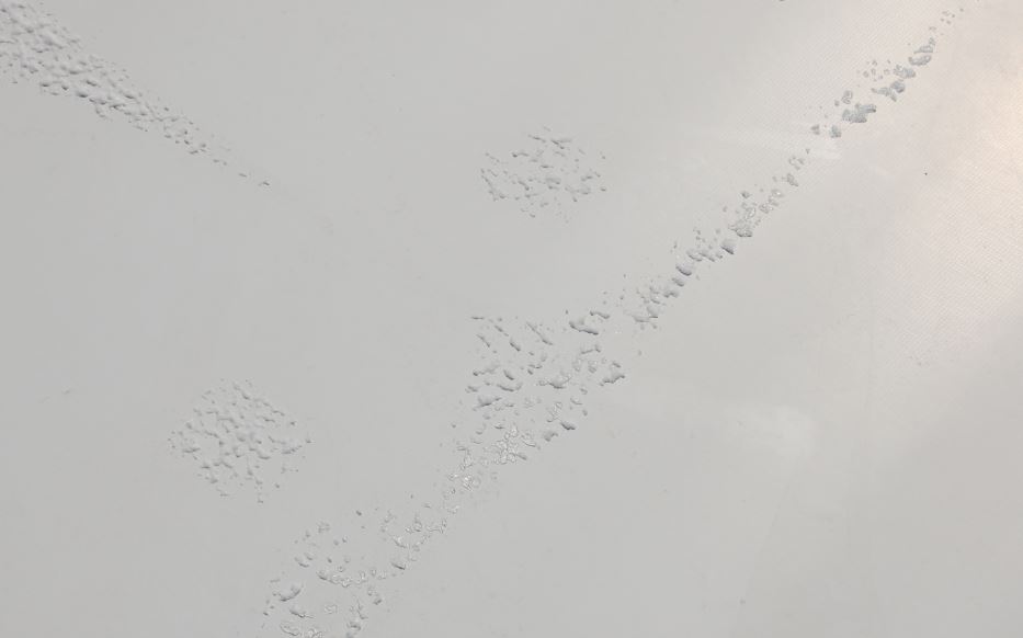
The most detrimental method of insulation attachment in regard to energy loss is when the insulation is mechanically fastened with the fasteners below the roof cover. Thermal bridging takes place from the conditioned interior to the exterior along the steel fastener. This can readily be observed on roofs with heavy frost and light snowfall, as the metal stress plates below the roof cover transfer heat from the interior to the membrane, which in turn melts the frost or snow above. (See Photo 4.)
The thermal values of roofs are compromised even more when a mechanically attached roof cover is installed. The volume of mechanical fasteners increases, as does the heat loss, which is not insignificant. Singh, Gulati, Srinivasan, and Bhandari in their study “Three-Dimensional Heat Transfer Analysis of Metal Fasteners in Roofing Assemblies”found an effective drop in thermal value of up to 48 percent when mechanical fasteners are used to attach roof covers. (See Photo 5). This research would suggest that for these types of roof systems, in order to meet the code-required effective thermal R-value, the designer needs to increase the required thermal R-value by 50 percent.
Recommendations to Increase Energy Savings
Code and standard bodies as well as governments around the world all agree that energy conservation is a laudable goal. Energy loss through the roof can be substantial, and an obvious location to focus on to prevent energy loss and thus create energy savings. The thermal layer works 24 hours a day, 7 days a week, 52 weeks a year. Compromises in the thermal layer will affect the performance of the insulation and decrease energy savings for years to come. Attention to installation methods and detailing transitions at roof edges, penetrations, walls and drains needs to be given in order to optimize the energy conservation potential of the roof system.
Based on empirical field observation of roof installations and forensic investigations, the following recommendations are made to increase the energy-saving potential of roof systems.
- Vapor and air barriers are often required or beneficial and should be specifically detailed at laps, penetrations, terminations and transitions to wall air barriers. (See Figure 1.) Call out on the drawings the contractor responsible for material termination so that this is clearly understood.
- The thermal layer (consisting of multiple layers of insulation) needs to be continuous without breaks or voids. Seal all voids at penetrations and perimeters with closed cell polyurethane sealant.
- Design insulation layers to be a minimum of two with offset joints.
- Select quality insulation materials. For polyisocyanurate, that would mean coated fiberglass facers. For mineral wool, that would mean high density.
- Attach insulation layers to the roof deck in a manner to eliminate thermal breaks. If mechanically fastening the insulation, the fasteners should be covered with another layer of insulation, cover board or both.
- Design roof covers that do not require mechanical fasteners below the membrane as an attachment method.
- Protect the thermal layer on top with cover boards and below with appropriate air and vapor barriers.
Saving limited fossil fuels and reducing carbon emissions is a worldwide goal. Designing and installing roof systems with a well thought out, detailed and executed thermal layer will move the building industry to a higher plane. Are you ready for the challenge?
About the author: Thomas W. Hutchinson, AIA, FRCI, RRC, CRP, CSI, is a principal of Hutchinson Design Group Ltd. in Barrington, Illinois. For more information, visit www.hutchinsondesigngroup.com.

Be the first to comment on "Designing Thermally Efficient Roof Systems"